Dealing with Radio Frequency Interference: Difference between revisions
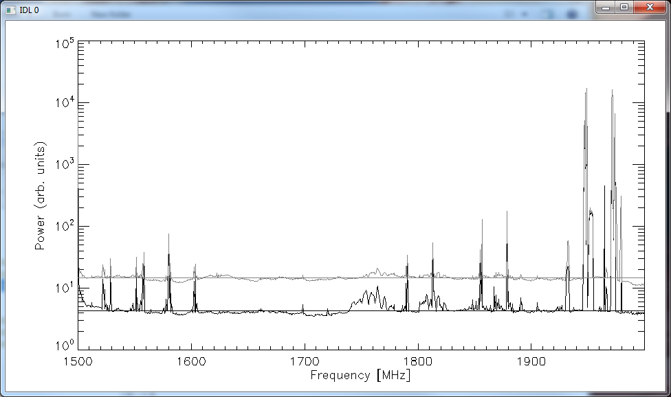
(Created page with "File:RFI1.png|thumb|400px|'''Fig. 1:''' Power level in the 1.5-2.0 GHz band for antenna 3 in the direction of strongest RFI. The black curve is the band power spectrum with...") |
No edit summary |
||
| (One intermediate revision by the same user not shown) | |||
| Line 3: | Line 3: | ||
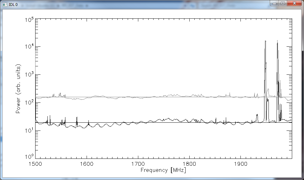
[[File:RFI2.png|thumb|400px|'''Fig. 2:''' Power level in the 1.5-2.0 GHz band for antenna 3 in the direction of weakest RFI. The curves are the same as in Fig. 1.]] | [[File:RFI2.png|thumb|400px|'''Fig. 2:''' Power level in the 1.5-2.0 GHz band for antenna 3 in the direction of weakest RFI. The curves are the same as in Fig. 1.]] | ||
The EOVSA system has been designed to work over the entire range 1-18 GHz. However, the cell-phone band near 2 GHz has gotten worse over time in the valley, and when testing of the new front ends began, we immediately found serious problems with Radio Frequency Interference (RFI) causing non-linearities in the system, particularly the optical link. This was especially problematic when pointing in the SW direction in the afternoon, but was basically unacceptable over the entire sky. Although we were aware of the problems between 1940-1980 MHz (see Figures 1 and 2), | The EOVSA system has been designed to work over the entire range 1-18 GHz. However, the cell-phone band near 2 GHz has gotten worse over time in the valley, and when testing of the new front ends began, we immediately found serious problems with Radio Frequency Interference (RFI) causing non-linearities in the system, particularly the optical link. This was especially problematic when pointing in the SW direction in the afternoon, but was basically unacceptable over the entire sky. Although we were aware of the problems between 1940-1980 MHz (see Figures 1 and 2), this initial assessment concluded that we only needed a notch filter on the more sensitive 27-m cooled receivers in order to block the RFI. The band below 2.2 GHz is also bad, although not shown in the figures. Notch filters to block the 1.9-2.2 GHz have been installed in the cooled receivers, but now we know that the small dishes also require such filters. Unfortunately, the filters we installed in the cooled receivers are much too large to fit in the already designed and constructed 2.1-m receivers. | ||
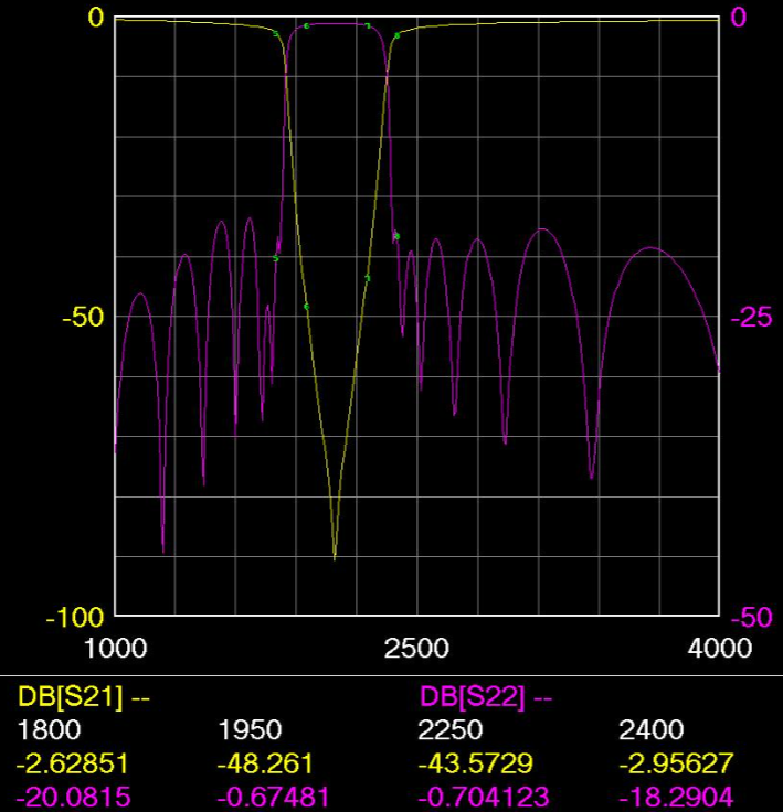
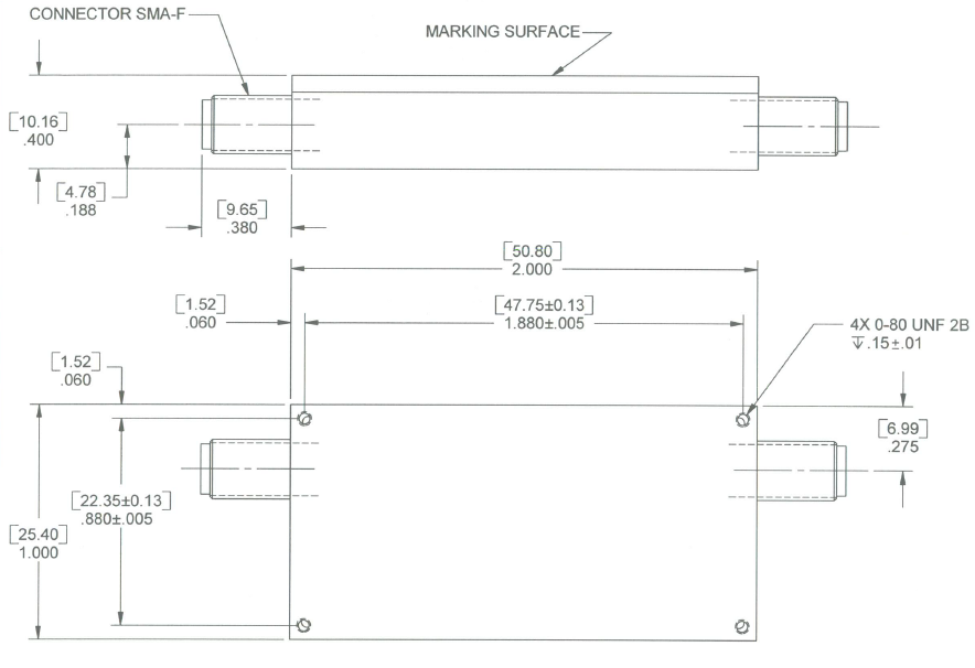
In order to continue with testing and commissioning, we purchased and installed high-pass filters that essential block everything below 2.5 GHz, and we have been running the array that way ever since. However, we are still interested in finding a solution via notch filters that would at least let us observe the 1-1.9 GHz band, and hopefully also recover some bandwidth between 2.2 and 2.5 GHz. To that end, we have requested quotes from several companies, one of which looks promising, as shown in Figure 3. An important aspect of the problem is that the notch filters (2 are required, one for each IF channel) must fit in the existing front-end box if we are to avoid having to redesign the front ends completely. These are already quite full, but the size of this filter (Figure 4) is 1 x 2 x 0.4 inches, and so we may be able to arrange them in the space available. We are placing an order for two of them, to test in one front end, and if the evaluation is positive, we will seek to order enough for the entire array (about $23 k). The specs are shown in tabular form below: | |||
===Specifications for Notch Filter=== | |||
<pre> | |||
Insertion Loss < 1.5 dBa 1,000 to 1,600 MHz | |||
Insertion Loss < 2.0 dBa 1,600 to 1,700 MHz | |||
Insertion Loss < 2.5 dBa 1,700 to 1,770 MHz | |||
Insertion Loss < 3.0 dBa 1,770 to 1,800 MHz | |||
Insertion Loss < 3.2 dBa 2,400 to 2,430 MHz | |||
Insertion Loss < 2.7 dBa 2,430 to 2,500 MHz | |||
Insertion Loss < 2.3 dBa 2,500 to 18,000 MHz | |||
VSWR < 2.0:1 1,000 to 1,900 & 2,400 to 18,000 | |||
Rejection -20 dBc min @ 1900 & 2300 MHz | |||
Rejection -30 dBc min @ 1950 to 2250 MHz | |||
SIZE 2.0 x1.0 X 0.40 | |||
</pre> | |||
If the filter meets these specs, and can fit into the front end box, we will recover some valuable parts of the RF band. --[[User:Dgary|Dgary]] ([[User talk:Dgary|talk]]) 16:58, 27 October 2016 (UTC) | |||
[[File:notch_filter_curve.png|thumb|left|400px|'''Fig. 3:''' Simulation of notch filter performance, for the filter we will evaluate.]] | |||
[[File:notch_filter_case.png|thumb|left|400px|'''Fig. 4:''' Dimensions of the notch filter.]] | |||
Latest revision as of 17:00, 27 October 2016

The EOVSA system has been designed to work over the entire range 1-18 GHz. However, the cell-phone band near 2 GHz has gotten worse over time in the valley, and when testing of the new front ends began, we immediately found serious problems with Radio Frequency Interference (RFI) causing non-linearities in the system, particularly the optical link. This was especially problematic when pointing in the SW direction in the afternoon, but was basically unacceptable over the entire sky. Although we were aware of the problems between 1940-1980 MHz (see Figures 1 and 2), this initial assessment concluded that we only needed a notch filter on the more sensitive 27-m cooled receivers in order to block the RFI. The band below 2.2 GHz is also bad, although not shown in the figures. Notch filters to block the 1.9-2.2 GHz have been installed in the cooled receivers, but now we know that the small dishes also require such filters. Unfortunately, the filters we installed in the cooled receivers are much too large to fit in the already designed and constructed 2.1-m receivers.
In order to continue with testing and commissioning, we purchased and installed high-pass filters that essential block everything below 2.5 GHz, and we have been running the array that way ever since. However, we are still interested in finding a solution via notch filters that would at least let us observe the 1-1.9 GHz band, and hopefully also recover some bandwidth between 2.2 and 2.5 GHz. To that end, we have requested quotes from several companies, one of which looks promising, as shown in Figure 3. An important aspect of the problem is that the notch filters (2 are required, one for each IF channel) must fit in the existing front-end box if we are to avoid having to redesign the front ends completely. These are already quite full, but the size of this filter (Figure 4) is 1 x 2 x 0.4 inches, and so we may be able to arrange them in the space available. We are placing an order for two of them, to test in one front end, and if the evaluation is positive, we will seek to order enough for the entire array (about $23 k). The specs are shown in tabular form below:
Specifications for Notch Filter
Insertion Loss                   < 1.5 dBa 1,000 to 1,600 MHz
Insertion Loss                   < 2.0 dBa 1,600 to 1,700 MHz
Insertion Loss                   < 2.5 dBa 1,700 to 1,770 MHz
Insertion Loss                   < 3.0 dBa 1,770 to 1,800 MHz

Insertion Loss                   < 3.2 dBa 2,400 to 2,430 MHz
Insertion Loss                   < 2.7 dBa 2,430 to 2,500 MHz
Insertion Loss                   < 2.3 dBa 2,500 to 18,000 MHz

VSWR                            <  2.0:1  1,000 to 1,900 & 2,400 to 18,000
Rejection                       -20 dBc min @ 1900 & 2300 MHz
Rejection                       -30 dBc min @ 1950 to 2250 MHz

SIZE                             2.0 x1.0 X 0.40
If the filter meets these specs, and can fit into the front end box, we will recover some valuable parts of the RF band. --Dgary (talk) 16:58, 27 October 2016 (UTC)


