Polarization Mixing Due to Feed Rotation: Difference between revisions
| (99 intermediate revisions by the same user not shown) | |||
| Line 110: | Line 110: | ||
\cos\chi_2\cos\chi_1 & \cos\chi_2\sin\chi_1 & \sin\chi_2\cos\chi_1 & \sin\chi_2\sin\chi_1 \\ | \cos\chi_2\cos\chi_1 & \cos\chi_2\sin\chi_1 & \sin\chi_2\cos\chi_1 & \sin\chi_2\sin\chi_1 \\ | ||
-a_1\cos\chi_2\sin\chi_1 & a_1\cos\chi_2\cos\chi_1 & -a_1\sin\chi_2\sin\chi_1 & a_1\sin\chi_2\cos\chi_1 \\ | -a_1\cos\chi_2\sin\chi_1 & a_1\cos\chi_2\cos\chi_1 & -a_1\sin\chi_2\sin\chi_1 & a_1\sin\chi_2\cos\chi_1 \\ | ||
-a_2\sin\chi_2\cos\chi_1 & -a_2\sin\chi_2\sin\chi_1 & a_2\cos\chi_2\cos\chi_1 & a_2\cos\chi_2\sin\chi_1 \\ | -a_2^*\sin\chi_2\cos\chi_1 & -a_2^*\sin\chi_2\sin\chi_1 & a_2^*\cos\chi_2\cos\chi_1 & a_2^*\cos\chi_2\sin\chi_1 \\ | ||
a_1a_2\sin\chi_2\sin\chi_1 & -a_1a_2\sin\chi_2\cos\chi_1 & -a_1a_2\cos\chi_2\sin\chi_1 & a_1a_2\cos\chi_2\cos\chi_1 | a_1a_2^*\sin\chi_2\sin\chi_1 & -a_1a_2^*\sin\chi_2\cos\chi_1 & -a_1a_2^*\cos\chi_2\sin\chi_1 & a_1a_2^*\cos\chi_2\cos\chi_1 | ||
\end{bmatrix} | \end{bmatrix} | ||
\begin{bmatrix} | \begin{bmatrix} | ||
| Line 150: | Line 150: | ||
<center><math> | <center><math> | ||
M_1 = | M_1 = I \otimes R_1 = \begin{bmatrix} | ||
1 & 0 \\ | 1 & 0 \\ | ||
0 & | 0 & 1 | ||
\end{bmatrix} \otimes \begin{bmatrix} | \end{bmatrix} \otimes \begin{bmatrix} | ||
\cos\chi_1 & \sin\chi_1 \\ | \cos\chi_1 & \sin\chi_1 \\ | ||
| Line 159: | Line 159: | ||
\begin{bmatrix} | \begin{bmatrix} | ||
\cos\chi_1 & 0 & \sin\chi_1 & 0 \\ | \cos\chi_1 & 0 & \sin\chi_1 & 0 \\ | ||
0 & | 0 & \cos\chi_1 & 0 & \sin\chi_1 \\ | ||
-\sin\chi_1 & 0 & \cos\chi_1 & 0 \\ | -\sin\chi_1 & 0 & \cos\chi_1 & 0 \\ | ||
0 & - | 0 & -\sin\chi_1 & 0 & \cos\chi_1 | ||
\end{bmatrix} | \end{bmatrix} | ||
</math></center> | </math></center> | ||
| Line 168: | Line 168: | ||
<center><math> | <center><math> | ||
M_2 = | M_2 = I \otimes R_2 = \begin{bmatrix} | ||
1 & 0 \\ | 1 & 0 \\ | ||
0 & | 0 & 1 | ||
\end{bmatrix} \otimes \begin{bmatrix} | \end{bmatrix} \otimes \begin{bmatrix} | ||
\cos\chi_2 & \sin\chi_2 \\ | \cos\chi_2 & \sin\chi_2 \\ | ||
| Line 176: | Line 176: | ||
\end{bmatrix} = | \end{bmatrix} = | ||
\begin{bmatrix} | \begin{bmatrix} | ||
\cos\chi_2 & 0 & \sin\chi_2 & 0 \\ | \cos\chi_2 & 0 & \sin\chi_2 & 0 \\ | ||
0 & | 0 & \cos\chi_2 & 0 & \sin\chi_2 \\ | ||
-\sin\chi_2 & 0 & \cos\chi_2 & 0 \\ | -\sin\chi_2 & 0 & \cos\chi_2 & 0 \\ | ||
0 & - | 0 & -\sin\chi_2 & 0 & \cos\chi_2 | ||
\end{bmatrix} | \end{bmatrix} | ||
</math></center> | </math></center> | ||
then form an overall matrix <math>M = M_1 M_2^T</math>. | then form an overall matrix | ||
<center><math>M = M_1 M_2^T = \begin{bmatrix} | |||
\cos\Delta\chi & 0 & \sin\Delta\chi & 0 \\ | |||
0 & \cos\Delta\chi & 0 & \sin\Delta\chi \\ | |||
-\sin\Delta\chi & 0 & \cos\Delta\chi & 0 \\ | |||
0 & -\sin\Delta\chi & 0 & \cos\Delta\chi | |||
\end{bmatrix} | |||
</math></center>, | |||
where <math>\Delta\chi = \chi_2 - \chi_1</math>. | |||
= Effect of | = Effect of an X - Y Delay = | ||
Regardless of how the math is done, we expect that the result should be dependent on the difference in angle, <math>\Delta\chi</math>, so as a practical solution let us simply replace <math>\chi_1</math> with <math>\Delta\chi</math> and proceed as in section 1. | |||
<center><math> | |||
\boldsymbol{e}_{A,out} = J_A\boldsymbol{e}_{A,in} = \begin{bmatrix} | |||
1 & 0 \\ | |||
0 & a_1 | |||
\end{bmatrix}\begin{bmatrix} | |||
\cos\Delta\chi & \sin\Delta\chi \\ | |||
-\sin\Delta\chi & \cos\Delta\chi | |||
\end{bmatrix} | |||
\begin{bmatrix} | |||
X_A \\ | |||
Y_A | |||
\end{bmatrix} | |||
\qquad\qquad | |||
\boldsymbol{e}_{B,out} = J_B\boldsymbol{e}_{B,in} = \begin{bmatrix} | |||
1 & 0 \\ | |||
0 & a_2 | |||
\end{bmatrix} | |||
\begin{bmatrix} | |||
X_B \\ | |||
Y_B | |||
\end{bmatrix} | |||
</math></center> | |||
and the cross-correlation is found by taking the outer product, i.e. | |||
<center><math> | |||
<\boldsymbol{e}_{A,out}\otimes\boldsymbol{e}^*_{B,out}> = J_A \otimes J^*_B<\boldsymbol{e}_{A,in}\otimes\boldsymbol{e}^*_{B,in}> | |||
</math></center> | |||
which relates the output polarization products to the input as | |||
<center><math> | |||
\begin{bmatrix} | |||
XX \\ | |||
XY \\ | |||
YX \\ | |||
YY | |||
\end{bmatrix}_{out} | |||
= | |||
\begin{bmatrix} | |||
\cos\Delta\chi & 0 & \sin\Delta\chi & 0 \\ | |||
0 & a_2^*\cos\Delta\chi & 0 & a_2^*\sin\Delta\chi \\ | |||
-a_1\sin\Delta\chi & 0 & a_1\cos\Delta\chi & 0 \\ | |||
0 & -a_1a_2^*\sin\Delta\chi & 0 & a_1a_2^*\cos\Delta\chi | |||
\end{bmatrix} | |||
\begin{bmatrix} | |||
XX \\ | |||
XY \\ | |||
YX \\ | |||
YY | |||
\end{bmatrix}_{in} \qquad\qquad (2) | |||
</math></center> | |||
Now consider that there is a "multi-band" delay on both antennas, <math>\tau_1</math> and <math>\tau_2</math>. Then (2) becomes: | |||
<center><math> | |||
\begin{bmatrix} | |||
XX \\ | |||
XY \\ | |||
YX \\ | |||
YY | |||
\end{bmatrix}_{out} | |||
= | |||
\begin{bmatrix} | |||
\cos\Delta\chi & 0 & \sin\Delta\chi & 0 \\ | |||
0 & e^{-2\pi if\tau_2}\cos\Delta\chi & 0 & e^{-2\pi if\tau_2}\sin\Delta\chi \\ | |||
-e^{2\pi if\tau_1}\sin\Delta\chi & 0 & e^{2\pi if\tau_1}\cos\Delta\chi & 0 \\ | |||
0 & -e^{2\pi if(\tau_1 - \tau_2)}\sin\Delta\chi & 0 & e^{2\pi if(\tau_1 - \tau_2)}\cos\Delta\chi | |||
\end{bmatrix} | |||
\begin{bmatrix} | |||
XX \\ | |||
XY \\ | |||
YX \\ | |||
YY | |||
\end{bmatrix}_{in}. \qquad\qquad (3) | |||
</math></center> | |||
The result agrees with our intuition: | |||
<center><math> | |||
\begin{align} | |||
XX_{out} &= \cos\Delta\chi XX_{in} + \sin\Delta\chi YX_{in} \qquad \qquad \qquad \text{(has no phase shift)}\\ | |||
XY_{out} &= (\cos\Delta\chi XY_{in} + \sin\Delta\chi YY_{in})e^{-2\pi if\tau_2} \qquad \text{(phase shift depends on} \;\tau_2 \text{)} \\ | |||
YX_{out} &= (\cos\Delta\chi YX_{in} - \sin\Delta\chi XX_{in})e^{2\pi if\tau_1} \qquad \text{(phase shift depends on} \;\tau_1 \text{)} \\ | |||
YY_{out} &= (\cos\Delta\chi YY_{in} - \sin\Delta\chi XY_{in})e^{2\pi if(\tau_1 - \tau_2)} \qquad \text{(phase shift depends on delay difference)} | |||
\end{align} \qquad\qquad (4) | |||
</math></center> | |||
This approach was implemented, to see how well it does in correcting for the effects of differential feed rotation, but the results were not good. The problem turns out not to be the approach, but the assumption that the X-Y delay is a constant with frequency. The next section describes the actual case, where the X-Y delay is considered in terms of a measured "delay phase." | |||
[ | = Another Look at X-Y Delays = | ||
Prior to doing the feed rotation correction, it is essential that any X-Y delays be measured and corrected. We have devised a calibration procedure in which we take data on a strong calibrator with the feeds parallel, then rotate the 27-m (antenna 14) feed so that they are perpendicular. For an unpolarized source, this results in signal on the XX and YY polarization channels in the first case, and on the XY and YX polarization channels in the second case. As a practical matter, this can be done on all antennas at once if a strong source is observed near 0 HA, ideally timed to start 20 min before 0 HA and completing 20 min after 0 HA. The source 2253+161 works well, as does 1229+006 (3C273). Two observations are needed | |||
:* one with the 27-m feed unrotated (gives parallel-feed data for all dishes, if done near 0 HA). Gives strong signal in XX and YY channels. [http://ovsa.njit.edu/phasecal/20170702/pcF20170702121949_2253+161.png Example] | |||
:* one with the 27-m feed rotated to -90 degrees (gives crossed-feed data for all dishes, if done near 0 HA). Gives strong signal in XY and YX channels. [http://ovsa.njit.edu/phasecal/20170702/pcF20170702115948_2253+161.png Example] | |||
Note that the feed should be rotated by -90, not 90, in order for the signs in the expressions below to be correct. | |||
[[File: | == Background == | ||
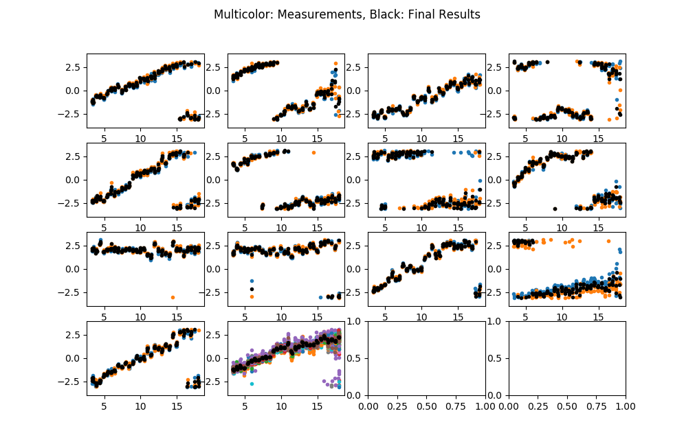
[[File: 20170702_delay-phase.png | thumb | 300px | '''Figure 1x:''' Example of delay phase measurement for 2017-07-02. Multiple measurements of the delay phase are possible, two for each of the small antennas and 26 for antenna 14. These are shown by the multicolor points. The average of the measurements are shown with black points.]] | |||
In order to correct for feed rotation, it is necessary to measure and correct for any differences in X vs. Y delay. We have devised a way of making this measurement by holding the small antenna feeds fixed and rotating the antenna 14 feed from 0-degree position angle (parallel to the small dish feeds) to -90 degrees position angle (perpendicular to the small dish feeds). In the 0-degree case, the X feeds are all parallel to each other, and the Y feeds are all parallel to each other. In the -90-degree case, the small-dish X feeds are parallel to the antenna 14 Y feed, and the small-dish Y feeds are parallel to the antenna 14 X feed. Comparing the parallel XX vs. crossed XY, the phases should be the same except for any non-zero X vs. Y delay on antenna 14, and a possible secular change in phase due to rotating the feed (<math>\xi_{rot}</math>). Comparing the parallel YY vs. crossed XY, on the other hand, the phases should be the same except for any non-zero X vs. Y delays on the small antennas, plus the effect of <math>\xi_{rot}</math>. Thus, <math>\xi_{rot}</math> = 0 on XX and YY measurements, and non-zero for XY and YX measurements. | |||
We can derive expressions by considering antenna-based phases on X polarization as <math>\phi(X_i) = \phi_i + \delta_{i14}\xi_{rot}</math> and on Y polarization as <math>\phi(Y_i) = \phi_i + d\phi_i + \delta_{i14}\xi_{rot}</math>, i.e. the Y phases are nominally the same as for X, except for a possible X-Y delay difference <math>\tau_i</math>, here written as delay phase <math>d\phi_i = 2\pi\tau_i f</math>. We are finding that this delay is a complicated function of frequency, so it is just as well to keep it in terms of phase. The <math>\xi_{rot}</math> term is only present on antenna 14, hence the use of the Kronecker <math>\delta</math>. As noted above, the term <math>\xi_{rot}</math> is zero if the antenna 14 feed is not rotated (i.e. for XX and YY measurements) and non-zero if it is (for XY and YX measurements). On a baseline <math>(i,j)</math>, then, the four polarization terms become: | |||
<center><math> | |||
\begin{align} | |||
\phi_{ij}(XX) &= \phi(X_j) - \phi(X_i) = \phi_j - \phi_i\\ | |||
\phi_{ij}(XY) &= \phi(Y_j) - \phi(X_i) = \phi_j + d\phi_j + \delta_{j14}\xi_{rot} - \phi_i\\ | |||
\phi_{ij}(YX) &= \phi(X_j) - \phi(Y_i) = \phi_j + \delta_{j14}\xi_{rot} - \phi_i - d\phi_i\\ | |||
\phi_{ij}(YY) &= \phi(Y_j) - \phi(Y_i) = \phi_j + d\phi_j - \phi_i - d\phi_i | |||
\end{align}\qquad\qquad (5) | |||
</math></center> | |||
We then examine the channel differences on baselines with antenna 14 (<math>j=14</math>), i.e. | |||
<center><math> | |||
\begin{align} | |||
\phi_{i14}(XY) - \phi_{i14}(XX) &= \phi_{14} + d\phi_{14} + \xi_{rot} - \phi_i - \phi_{14} + \phi_i &= d\phi_{14} + \xi_{rot}, \\ | |||
\phi_{i14}(YY) - \phi_{i14}(YX) &= \phi_{14} + d\phi_{14} - \phi_i - d\phi_i - \phi_{14} - \xi_{rot} + \phi_i + d\phi_i &= d\phi_{14} - \xi_{rot}, \\ | |||
\phi_{i14}(XX) - \phi_{i14}(YX) &= \phi_{14} - \phi_i - \phi_{14} - \xi_{rot} + \phi_i + d\phi_i &= d\phi_i - \xi_{rot}, \\ | |||
\phi_{i14}(XY) - \phi_{i14}(YY) &= \phi_{14} + d\phi_{14} + \xi_{rot} - \phi_i - \phi_{14} - d\phi_{14} + \phi_i + d\phi_i &= d\phi_i + \xi_{rot}. | |||
\end{align} | |||
</math></center> | |||
Consequently, we can solve redundantly in two ways for the antenna-based delay phases: | |||
<center><math> | |||
\begin{align} | |||
d\phi_i &= \phi_{i14}(XX) - \phi_{i14}(YX) + \xi_{rot} = \phi_{i14}(XY) - \phi_{i14}(YY) - \xi_{rot}, \\ | |||
d\phi_{14} &= \phi_{i14}(XY) - \phi_{i14}(XX) - \xi_{rot} = \phi_{i14}(YY) - \phi_{i14}(YX) + \xi_{rot}, | |||
\end{align}\qquad\qquad (6) | |||
</math></center> | |||
where we specifically use <math>j=14</math> to emphasize that this quantity for all antennas should be the same value, because the measurements are all baselines with antenna 14. Both of these give the same expression: | |||
<center><math> | |||
2\xi_{rot} = \phi_{i14}(XY) - \phi_{i14}(YY) - \phi_{i14}(XX) + \phi_{i14}(YX), | |||
</math></center> | |||
which, when evaluated for the thirteen different measurements do indeed give the same result within statistical variations. Care must be taken to do an appropriate average to take care of the <math>2\pi</math> phase ambiguity. One way to do this is form unit vectors and sum them, then find the phase of the summed vector. In Python, the following expression calculates an average phase phi_avg from the 13 individual measurements phi, where the sum over index 0 is over antennas: | |||
phi_avg = np.angle(np.sum(np.exp(1j*phi),0)) | |||
Once we have this average value of <math>\xi_{rot}</math>, the equations (6) give two measurements for each antenna for <math>d\phi_i</math>, and the 26 measurements for antenna 14 for <math>d\phi_{14}</math>, which can be averaged in the same manner. | |||
'''Figure 1x''' shows the results for a measurement on 2017-07-02. | |||
== Applying the Measurements == | |||
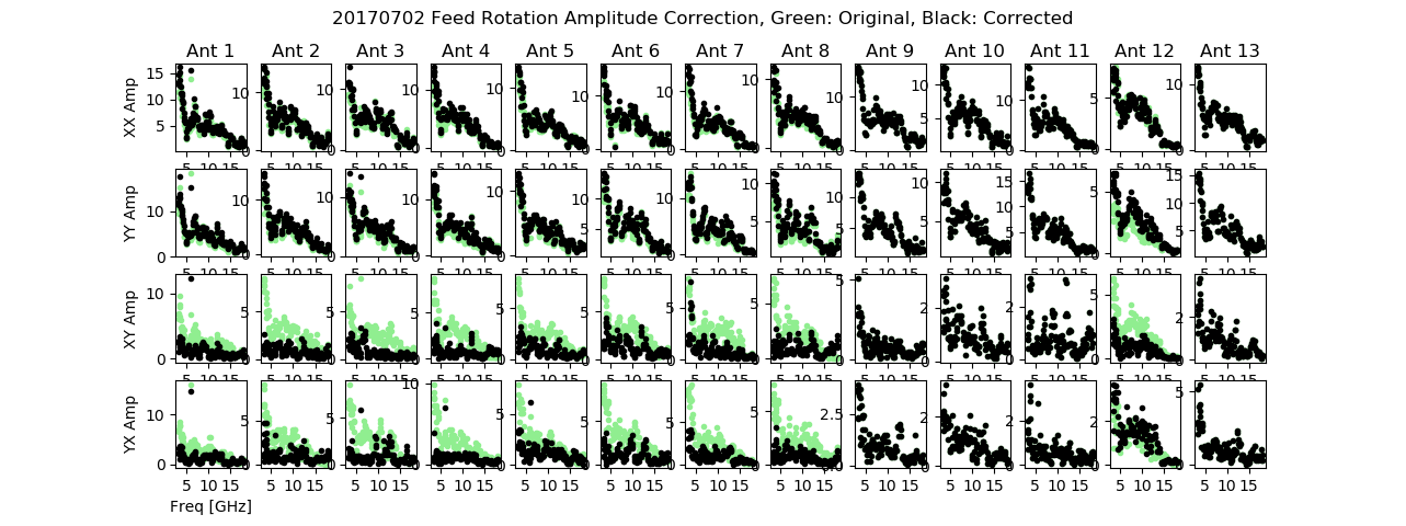
[[File: 20170702-amp-correction.png | thumb | 600px | '''Figure 2x:''' Amplitude vs frequency for channels XX, YY, XY and YX, on ants 1-13, before (green) and after (black) correction for feed rotation.]] | |||
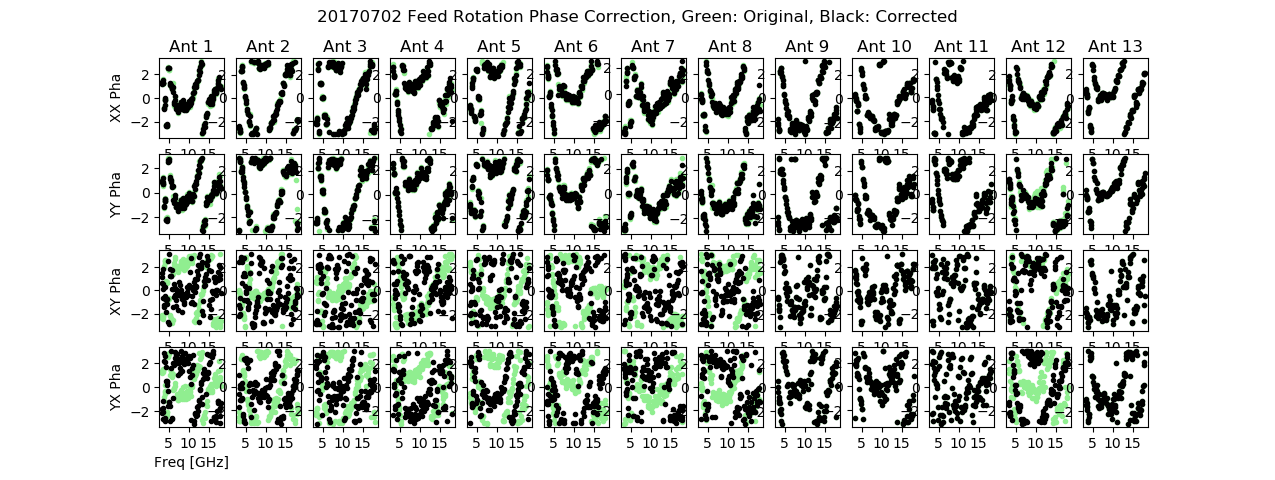
[[File: 20170702-phase-correction.png | thumb | 600px | '''Figure 3x:''' Phase vs frequency for channels XX, YY, XY and YX, on ants 1-13, before (green) and after (black) correction for feed rotation.]] | |||
Once we have these, we can apply corrections to each of the polarization channels, and then do the feed rotation correction. The corrections are done to data taken in a normal way, without rotating the 27-m feed. The application of the correction is found by removing the effects of the delays and rotations in equation (5): | |||
<center><math> | |||
\begin{align} | |||
\phi_{ij}(XX)' &= \phi_{ij}(XX),\quad\text{no correction} \\ | |||
\phi_{ij}(XY)' &= \phi_{ij}(XY) - d\phi_j - \delta_{j14}\xi_{rot}, \\ | |||
\phi_{ij}(YX)' &= \phi_{ij}(YX) + d\phi_i - \delta_{j14}\xi_{rot} + \pi, \\ | |||
\phi_{ij}(YY)' &= \phi_{ij}(YY) + d\phi_i - d\phi_j, | |||
\end{align}\qquad (6) | |||
</math></center> | |||
where the third term has an offset of <math>\pi</math> because this term should be flipped for negative parallactic angle, i.e. should be <math>\phi_{ij}(YX) = \phi_j - \phi_i + \pi</math>. Again, the Kronecker <math>\delta</math> indicates the fact that this term is applied only for baselines involving antenna 14. After the corrections are applied, we have | |||
<center><math> | |||
\begin{align} | |||
\phi_{ij}(XX)' &= \phi_j - \phi_i \\ | |||
\phi_{ij}(XY)' &= \phi_j - \phi_i, \\ | |||
\phi_{ij}(YX)' &= \phi_j - \phi_i + \pi, \\ | |||
\phi_{ij}(YY)' &= \phi_j - \phi_i. | |||
\end{align} | |||
</math></center> | |||
I tried applying the feed rotation correction for data taken on 2017-07-02, and it does seem to work. '''Figures 2x''' and '''3x''' show the amplitude and phase on all baselines with Ant 14, with light green for data before correction and black for after correction. For ants 1-8 and 12, the XX and YY amplitudes have increased a bit, while the XY and YX amplitudes are much reduced. The corresponding phases are slightly improved in XX and YY, and noise-like for XY and YX (less so on YX for some antennas). For the other antennas, no correction was made since those feeds are already parallel to Ant 14. | |||
The proof of this scheme will be seen when we observe a calibrator for many hours while the parallactic angle changes over HA, and then see that the amplitude time profiles become steady and well behaved. | |||
== | Ultimately, the X-Y delays will need to be measured periodically (especially if the correlator is rebooted or X and Y delays are changed for other reasons), and then stored as a new calibration type in the SQL database. | ||
== Comparison with the Mathematical Description in the Earlier Section == | |||
We now want to see how this compares with the mathematical development in the previous section. It turns out that they are the same, as long as we rewrite the expression <math>2\pi f\tau_i = \phi_i - \pi/2</math>. To see this, first write the corrections in equation (6) in matrix form: | |||
<center><math> | |||
\begin{bmatrix} | |||
XX \\ | |||
XY \\ | |||
YX \\ | |||
YY | |||
\end{bmatrix}_{in} | |||
= | |||
\begin{bmatrix} | |||
\cos\Delta\chi & 0 & -\sin\Delta\chi & 0 \\ | |||
0 & \cos\Delta\chi & 0 & -\sin\Delta\chi \\ | |||
\sin\Delta\chi & 0 & \cos\Delta\chi & 0 \\ | |||
0 & \sin\Delta\chi & 0 & \cos\Delta\chi | |||
\end{bmatrix} | |||
\begin{bmatrix} | |||
1 & 0 & 0 & 0 \\ | |||
0 & e^{-i(d\phi_j - \pi/2)} & 0 & 0 \\ | |||
0 & 0 & e^{i(d\phi_i - \pi/2)} & 0 \\ | |||
0 & 0 & 0 & e^{i(d\phi_i - d\phi_j)} | |||
\end{bmatrix} | |||
\begin{bmatrix} | |||
XX \\ | |||
XY \\ | |||
YX \\ | |||
YY | |||
\end{bmatrix}_{out} | |||
</math></center> | |||
where now this is the correction applied to the measured (<math>out</math>) data to covert it to the expected (<math>in</math>) data, and hence is the inverse of the matrix (2) in the previous section. Expanding the matrix product, this is | |||
<center><math> | |||
\begin{bmatrix} | |||
XX \\ | |||
XY \\ | |||
YX \\ | |||
YY | |||
\end{bmatrix}_{in} | |||
= | |||
\begin{bmatrix} | |||
\cos\Delta\chi & 0 & -e^{i(d\phi_i - \pi/2)}\sin\Delta\chi & 0 \\ | |||
0 & e^{-i(d\phi_j - \pi/2)}\cos\Delta\chi & 0 & -e^{i(d\phi_i - d\phi_j)}\sin\Delta\chi \\ | |||
\sin\Delta\chi & 0 & e^{i(d\phi_i - \pi/2)}\cos\Delta\chi & 0 \\ | |||
0 & e^{-i(d\phi_j - \pi/2)}\sin\Delta\chi & 0 & e^{i(d\phi_i - d\phi_j)}\cos\Delta\chi | |||
\end{bmatrix} | |||
\begin{bmatrix} | |||
XX \\ | |||
XY \\ | |||
YX \\ | |||
YY | |||
\end{bmatrix}_{out} | |||
</math></center> | |||
and converting back to <math>\tau_i</math>, it becomes: | |||
<center><math> | |||
\begin{bmatrix} | |||
XX \\ | |||
XY \\ | |||
YX \\ | |||
YY | |||
\end{bmatrix}_{in} | |||
= | |||
\begin{bmatrix} | |||
\cos\Delta\chi & 0 & -e^{2\pi if\tau_i}\sin\Delta\chi & 0 \\ | |||
0 & e^{-2\pi if\tau_j}\cos\Delta\chi & 0 & -e^{2\pi if(\tau_i-\tau_j)}\sin\Delta\chi \\ | |||
\sin\Delta\chi & 0 & e^{i2\pi f\tau_i}\cos\Delta\chi & 0 \\ | |||
0 & e^{-2\pi if\tau_j}\sin\Delta\chi & 0 & e^{2\pi if(\tau_i-\tau_j)}\cos\Delta\chi | |||
\end{bmatrix} | |||
\begin{bmatrix} | |||
XX \\ | |||
XY \\ | |||
YX \\ | |||
YY | |||
\end{bmatrix}_{out}\qquad\qquad (7) | |||
</math></center> | |||
which is precisely the inverse of (3). | |||
= AzEl Antenna Axis Offset = | |||
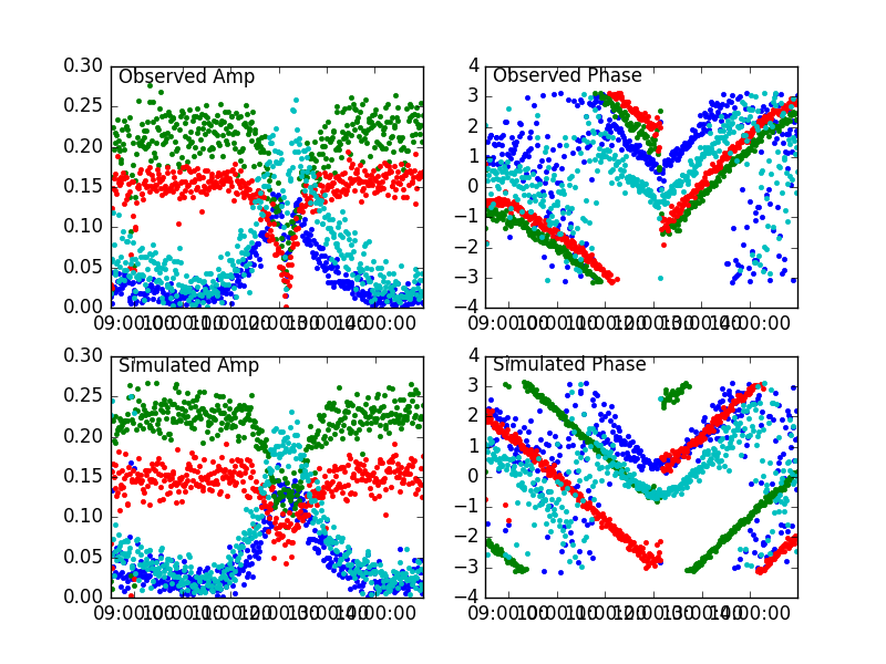
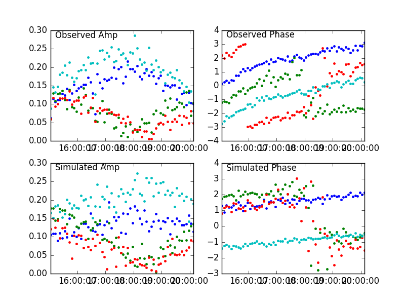
[[File:3C84_cos-el-rotation.png|right|thumb|300px|'''Fig. 9:''' Observations and simulation of amplitude and phase on 3C84 for baseline Ant 1-14, where a phase shift proportional to <math>{2\pi\over\lambda} \cos E</math> is applied. The agreement is reasonably good except for some curvature, which could be residual baseline error.]] | [[File:3C84_cos-el-rotation.png|right|thumb|300px|'''Fig. 9:''' Observations and simulation of amplitude and phase on 3C84 for baseline Ant 1-14, where a phase shift proportional to <math>{2\pi\over\lambda} \cos E</math> is applied. The agreement is reasonably good except for some curvature, which could be residual baseline error.]] | ||
| Line 223: | Line 439: | ||
[[File:3C273_cos-el-rotation.png|right|thumb|300px|'''Fig. 10:''' Observations and simulation of amplitude and phase on 3C273 for baseline Ant 1-14, where a phase shift proportional to <math>{2\pi\over\lambda} \cos E</math> is applied. The agreement is reasonably good, except for some curvature at negative hour angle, which could be residual baseline error.]] | [[File:3C273_cos-el-rotation.png|right|thumb|300px|'''Fig. 10:''' Observations and simulation of amplitude and phase on 3C273 for baseline Ant 1-14, where a phase shift proportional to <math>{2\pi\over\lambda} \cos E</math> is applied. The agreement is reasonably good, except for some curvature at negative hour angle, which could be residual baseline error.]] | ||
Dr. Avinash Deshpande (Raman Research Institute, Bangalore -- Thanks to Dr. Ananthakrishnan for contacting him) confirms that no phase rotation is expected for the parallactic correction, aside from the 180-degree phase jump at the meridian crossing. He suggests that a non-intersecting axis is | During our investigation of the parallactic angle correction, we noted a "V"-shaped dependence of phase on HA, for the AzEl baselines with Ant 14, that cannot be due to parallactic angle. Dr. Avinash Deshpande (Raman Research Institute, Bangalore -- ''Thanks to Dr. Ananthakrishnan for contacting him'') confirms that no phase rotation is expected for the parallactic correction, aside from the 180-degree phase jump at the meridian crossing. He suggests that a non-intersecting axis is the cause, and this was confirmed. He notes that the effect of non-intersecting axes is a phase rotation of | ||
<center><math>{2\pi\over\lambda} d\cos E</math></center> | <center><math>{2\pi\over\lambda} d\cos E</math></center> | ||
where <math>E</math> is the elevation angle, and <math>d</math> is the offset distance. As a test, I applied this function, using | where <math>E</math> is the elevation angle, and <math>d</math> is the offset distance. As a test, I applied this function, using d = 11.5 cm (based on the apparent phase variation in the observed phases), and obtained the results in '''Figures 9 and 10'''. Although the observed phases show a bit more curvature than the simulation, this was found to be due to residual baseline errors. | ||
=== Further update === | === Further update === | ||
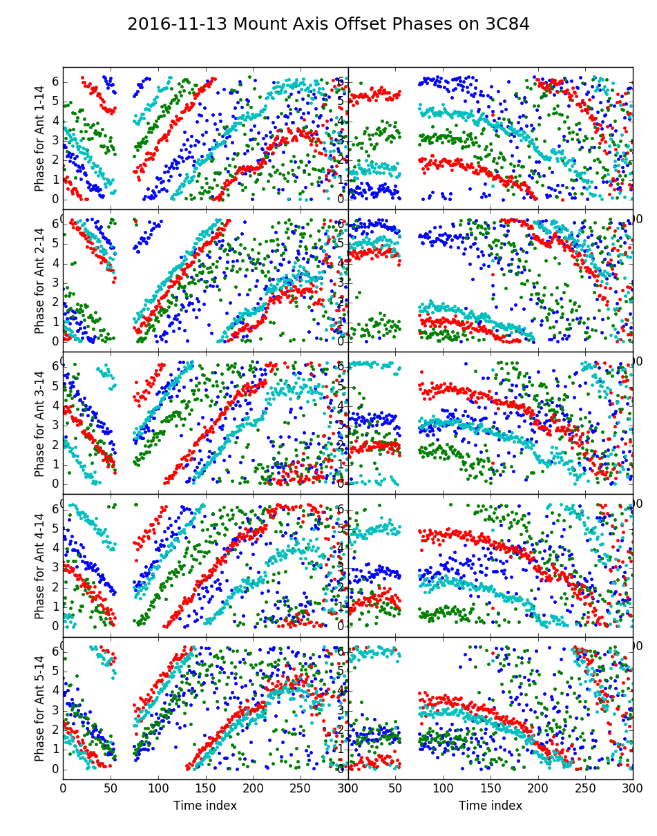
[[File:3C84_cos-el-correction.png|left|thumb|300px|'''Fig. 11:''' Observations and phase-corrected observations for 3C84 taken on 2016-11-13, where d = 15.2 cm was applied. Shown are Ant 1-5 baselines with Ant 14. The remaining phase variations are consistent with a residual Bx baseline error.]] | [[File:3C84_cos-el-correction.png|left|thumb|300px|'''Fig. 11:''' Observations and phase-corrected observations for 3C84 taken on 2016-11-13, where d = 15.2 cm was applied. Shown are Ant 1-5 baselines with Ant 14. The remaining phase variations are consistent with a residual Bx baseline error.]] | ||
On 2016 Nov 13, new observations of 3C84 were taken, and the correction for the axis offset (d = 15.2 cm) | On 2016 Nov 13, new observations of 3C84 were taken, and the correction for the axis offset (d = 15.2 cm) was applied, as shown in '''Figure 11''' (at left). It appears that this correction works well, and that there is a residual baseline error on each of the antennas due to the fact that they were originally determined without the axis-offset correction. --[[User:Dgary|Dgary]] ([[User talk:Dgary|talk]]) 14:20, 15 November 2016 (UTC) | ||
This change was permanently instituted in DPP_PROCESS_STATEFRAME.f90 on 2016-11-16. | |||
Latest revision as of 12:32, 10 July 2020
Explanation of Polarization Mixing
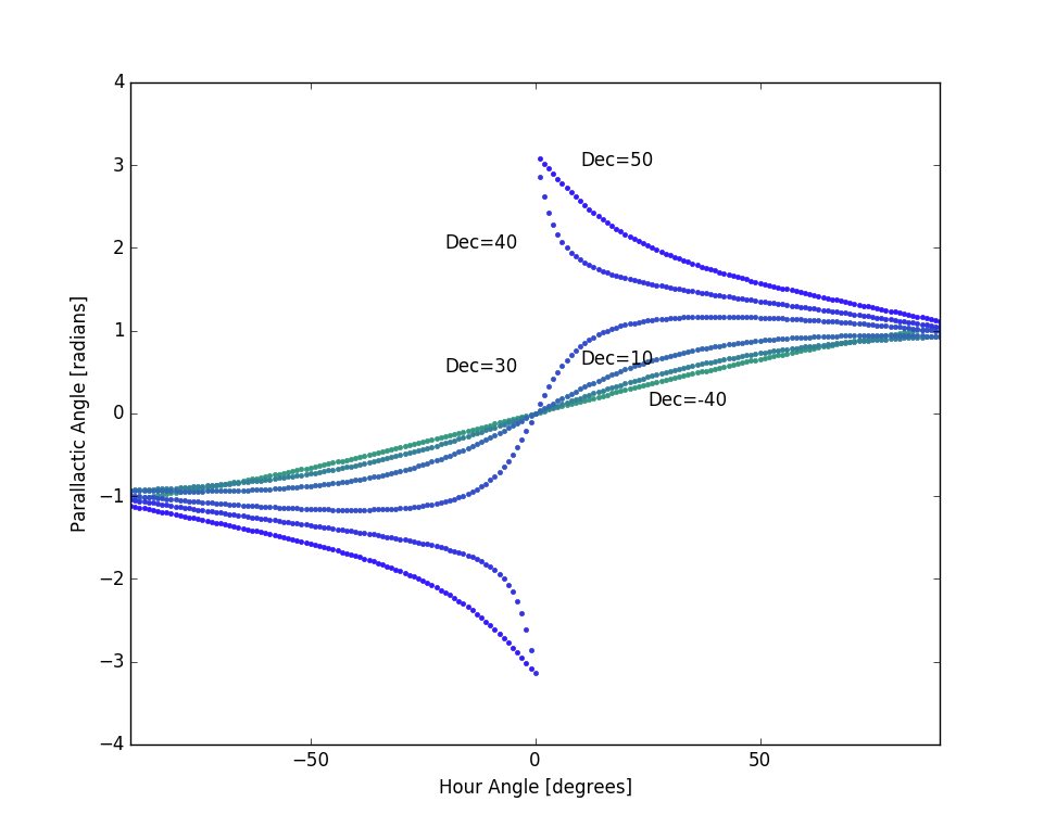
The newer 2.1-m antennas [Ants 1-8 and 12] have AzEl (azimuth-elevation) mounts (also referred to as AltAz; the terms Altitude and Elevation are used synonymously), which means that their crossed linear feeds have a constant angle relative to the horizon (the axis of rotation being at the zenith). The older 2.1-m antennas [Ants 9-11 and 13], and the 27-m antenna [Ant 14], have Equatorial mounts, which means that their crossed linear feeds have a constant angle with respect to the celestial equator, the axis of rotation being at the north celestial pole. Thus, the celestial coordinate system is tilted by the local co-latitude (complement of the latitude). This tilt results in a relative feed rotation between the 27-m antenna and the AzEl mounts, but not between the 27-m and the older equatorial mounts. This angle is called the "parallactic angle," and is given by:
where is the site latitude, is the Azimuth angle [0 north], and is the Elevation angle [0 on horizon]. This function obviously changes with position on the sky, and as we follow a celestial source (e.g. the Sun) across the sky this rotation angle is continuously changing in a surprisingly complex manner as shown in Figure 1. Note that at zero hour angle for declinations less than the local latitude (37.233 degrees at OVRO), but is at higher declinations.
The crossed linear dipole feeds on all antennas are oriented with the X-feed as shown in Figure 2, at 45-degrees from the horizontal, when the antenna is pointed at 0 hour angle. This is the view as seen looking down at the feed from the dish side, although since the feeds are at the prime focus this is the same as the view projected onto the sky. At other positions, the feeds on the AzEl antennas experience a rotation by angle relative to the equatorial antennas.
Because of this rotation, the normal polarization products XX, XY, YX and YY on baselines with dissimilar antennas (one AzEl and the other equatorial) become mixed. The effect of this admixture can be written by the use of Jones matrices (see Hamaker, Bregman & Sault (1996) for a complete description). Consider antenna A whose feed orientation is rotated by , cross-correlated with antenna B with unrotated feed. The corresponding Jones matrices, acting on signal vector are:
and the cross-correlation is found by taking the outer product, i.e.
which relates the output polarization products to the input as
where we have dropped the subscripts and complex conjugate notation for brevity. Of course, there are other effects such as unequal gains and cross-talk between feeds that are also at play, but for now we ignore those and focus only on the effect of this polarization mixing due to the parallactic angle.
Absolute vs. Relative Angle of Rotation
However, the above description fails when we consider a rotation on both antennas, so that
In this case, performing the outer product gives:
whereas intuitively we want something like:
which becomes the identity matrix when , i.e. when the feeds on two antennas of a baseline are parallel. The difference seems to be that the earlier expression evaluates to components of X and Y in an absolute coordinate frame, whereas we are interested only the difference in angle of the feeds in a relative coordinate frame. This choice no doubt has implications for measuring Stokes Q and U, but for solar data we are not concerned with linear polarization.
One way to achieve this in the framework of Jones matrices is to form Mueller matrices from the outer-product of the rotation times the gain matrix:
and
then form an overall matrix
,
where .
Effect of an X - Y Delay
Regardless of how the math is done, we expect that the result should be dependent on the difference in angle, , so as a practical solution let us simply replace with and proceed as in section 1.
and the cross-correlation is found by taking the outer product, i.e.
which relates the output polarization products to the input as
Now consider that there is a "multi-band" delay on both antennas, and . Then (2) becomes:
The result agrees with our intuition:
This approach was implemented, to see how well it does in correcting for the effects of differential feed rotation, but the results were not good. The problem turns out not to be the approach, but the assumption that the X-Y delay is a constant with frequency. The next section describes the actual case, where the X-Y delay is considered in terms of a measured "delay phase."
Another Look at X-Y Delays
Prior to doing the feed rotation correction, it is essential that any X-Y delays be measured and corrected. We have devised a calibration procedure in which we take data on a strong calibrator with the feeds parallel, then rotate the 27-m (antenna 14) feed so that they are perpendicular. For an unpolarized source, this results in signal on the XX and YY polarization channels in the first case, and on the XY and YX polarization channels in the second case. As a practical matter, this can be done on all antennas at once if a strong source is observed near 0 HA, ideally timed to start 20 min before 0 HA and completing 20 min after 0 HA. The source 2253+161 works well, as does 1229+006 (3C273). Two observations are needed
- one with the 27-m feed unrotated (gives parallel-feed data for all dishes, if done near 0 HA). Gives strong signal in XX and YY channels. Example
- one with the 27-m feed rotated to -90 degrees (gives crossed-feed data for all dishes, if done near 0 HA). Gives strong signal in XY and YX channels. Example
Note that the feed should be rotated by -90, not 90, in order for the signs in the expressions below to be correct.
Background
In order to correct for feed rotation, it is necessary to measure and correct for any differences in X vs. Y delay. We have devised a way of making this measurement by holding the small antenna feeds fixed and rotating the antenna 14 feed from 0-degree position angle (parallel to the small dish feeds) to -90 degrees position angle (perpendicular to the small dish feeds). In the 0-degree case, the X feeds are all parallel to each other, and the Y feeds are all parallel to each other. In the -90-degree case, the small-dish X feeds are parallel to the antenna 14 Y feed, and the small-dish Y feeds are parallel to the antenna 14 X feed. Comparing the parallel XX vs. crossed XY, the phases should be the same except for any non-zero X vs. Y delay on antenna 14, and a possible secular change in phase due to rotating the feed (). Comparing the parallel YY vs. crossed XY, on the other hand, the phases should be the same except for any non-zero X vs. Y delays on the small antennas, plus the effect of . Thus, = 0 on XX and YY measurements, and non-zero for XY and YX measurements.
We can derive expressions by considering antenna-based phases on X polarization as and on Y polarization as , i.e. the Y phases are nominally the same as for X, except for a possible X-Y delay difference , here written as delay phase . We are finding that this delay is a complicated function of frequency, so it is just as well to keep it in terms of phase. The term is only present on antenna 14, hence the use of the Kronecker . As noted above, the term is zero if the antenna 14 feed is not rotated (i.e. for XX and YY measurements) and non-zero if it is (for XY and YX measurements). On a baseline , then, the four polarization terms become:
We then examine the channel differences on baselines with antenna 14 (), i.e.
Consequently, we can solve redundantly in two ways for the antenna-based delay phases:
where we specifically use to emphasize that this quantity for all antennas should be the same value, because the measurements are all baselines with antenna 14. Both of these give the same expression:
which, when evaluated for the thirteen different measurements do indeed give the same result within statistical variations. Care must be taken to do an appropriate average to take care of the phase ambiguity. One way to do this is form unit vectors and sum them, then find the phase of the summed vector. In Python, the following expression calculates an average phase phi_avg from the 13 individual measurements phi, where the sum over index 0 is over antennas:
phi_avg = np.angle(np.sum(np.exp(1j*phi),0))
Once we have this average value of , the equations (6) give two measurements for each antenna for , and the 26 measurements for antenna 14 for , which can be averaged in the same manner.
Figure 1x shows the results for a measurement on 2017-07-02.
Applying the Measurements
Once we have these, we can apply corrections to each of the polarization channels, and then do the feed rotation correction. The corrections are done to data taken in a normal way, without rotating the 27-m feed. The application of the correction is found by removing the effects of the delays and rotations in equation (5):
where the third term has an offset of because this term should be flipped for negative parallactic angle, i.e. should be . Again, the Kronecker indicates the fact that this term is applied only for baselines involving antenna 14. After the corrections are applied, we have
I tried applying the feed rotation correction for data taken on 2017-07-02, and it does seem to work. Figures 2x and 3x show the amplitude and phase on all baselines with Ant 14, with light green for data before correction and black for after correction. For ants 1-8 and 12, the XX and YY amplitudes have increased a bit, while the XY and YX amplitudes are much reduced. The corresponding phases are slightly improved in XX and YY, and noise-like for XY and YX (less so on YX for some antennas). For the other antennas, no correction was made since those feeds are already parallel to Ant 14.
The proof of this scheme will be seen when we observe a calibrator for many hours while the parallactic angle changes over HA, and then see that the amplitude time profiles become steady and well behaved.
Ultimately, the X-Y delays will need to be measured periodically (especially if the correlator is rebooted or X and Y delays are changed for other reasons), and then stored as a new calibration type in the SQL database.
Comparison with the Mathematical Description in the Earlier Section
We now want to see how this compares with the mathematical development in the previous section. It turns out that they are the same, as long as we rewrite the expression . To see this, first write the corrections in equation (6) in matrix form:
where now this is the correction applied to the measured () data to covert it to the expected () data, and hence is the inverse of the matrix (2) in the previous section. Expanding the matrix product, this is
and converting back to , it becomes:
which is precisely the inverse of (3).
AzEl Antenna Axis Offset
During our investigation of the parallactic angle correction, we noted a "V"-shaped dependence of phase on HA, for the AzEl baselines with Ant 14, that cannot be due to parallactic angle. Dr. Avinash Deshpande (Raman Research Institute, Bangalore -- Thanks to Dr. Ananthakrishnan for contacting him) confirms that no phase rotation is expected for the parallactic correction, aside from the 180-degree phase jump at the meridian crossing. He suggests that a non-intersecting axis is the cause, and this was confirmed. He notes that the effect of non-intersecting axes is a phase rotation of
where is the elevation angle, and is the offset distance. As a test, I applied this function, using d = 11.5 cm (based on the apparent phase variation in the observed phases), and obtained the results in Figures 9 and 10. Although the observed phases show a bit more curvature than the simulation, this was found to be due to residual baseline errors.
Further update
On 2016 Nov 13, new observations of 3C84 were taken, and the correction for the axis offset (d = 15.2 cm) was applied, as shown in Figure 11 (at left). It appears that this correction works well, and that there is a residual baseline error on each of the antennas due to the fact that they were originally determined without the axis-offset correction. --Dgary (talk) 14:20, 15 November 2016 (UTC)
This change was permanently instituted in DPP_PROCESS_STATEFRAME.f90 on 2016-11-16.


![{\displaystyle {\boldsymbol {e}}_{in}=[X,Y]}](https://wikimedia.org/api/rest_v1/media/math/render/svg/bc4eeebe0b92120f842f54a160b57734dc5f6b5e)


