Polarization Calibration: Difference between revisions
No edit summary |
No edit summary |
||
| Line 1: | Line 1: | ||
== Linear to Circular Conversion == | == Linear to Circular Conversion == | ||
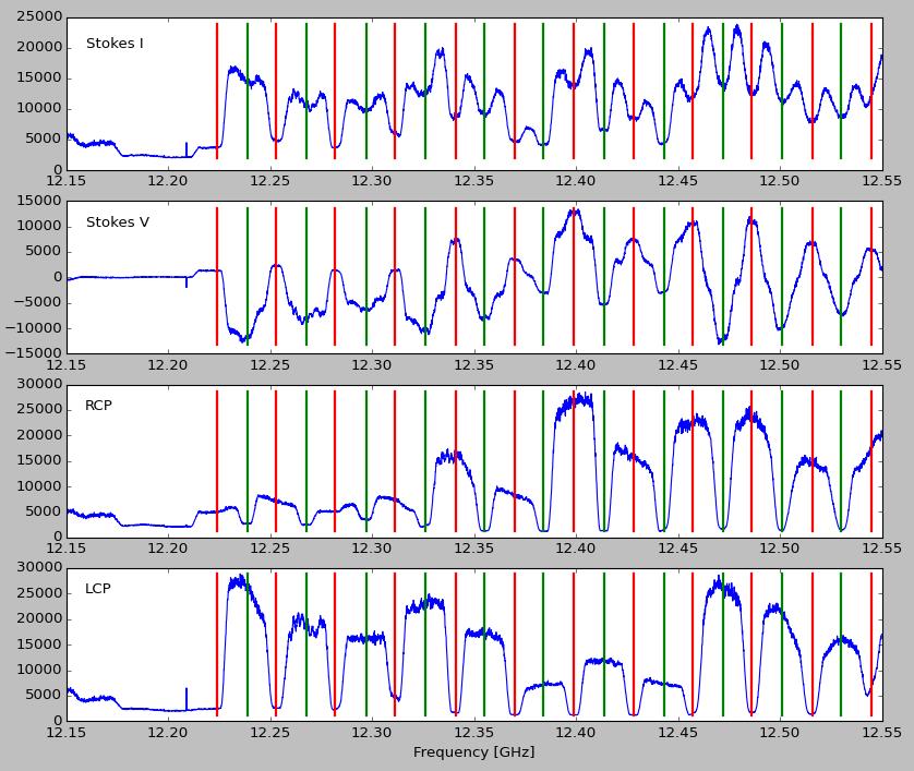
[[File:Linear_to_Circular_Conversion_Figure1.jpg|thumb| | [[File:Linear_to_Circular_Conversion_Figure1.jpg|thumb|400px|Figure 1: Amplitudes of Stokes I, Stokes V, RCP and LCP for Ciel-2 satellite. The red vertical lines show the center of RCP channels, while the green vertical lines show the center of LCP channels. There is pretty good separation of RCP and LCP at lower and higher frequencies in the range, but around 12.4 GHz the polarization has switched and is mis-assigned.]] | ||
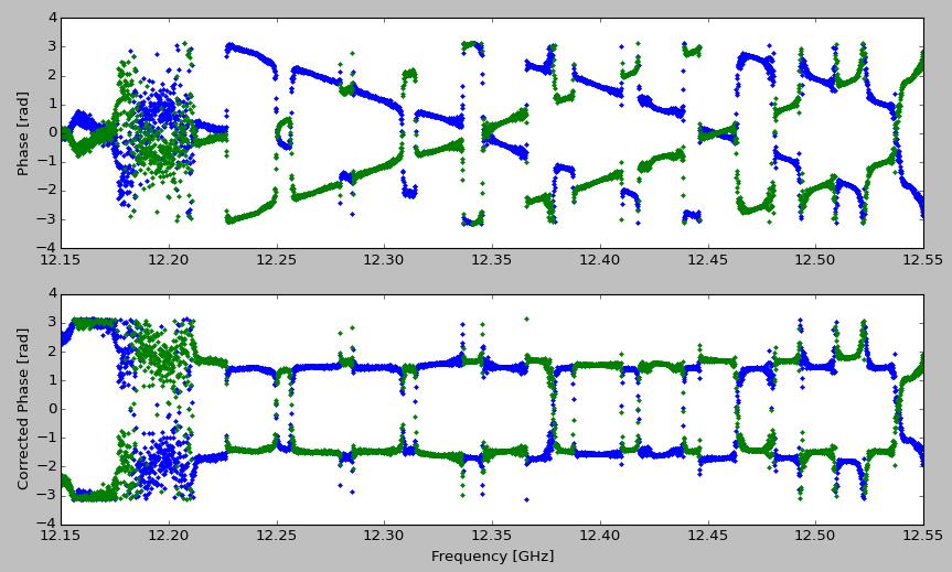
[[File:Linear_to_Circular_Conversion_Figure2.jpg|thumb| | [[File:Linear_to_Circular_Conversion_Figure2.jpg|thumb|400px|Figure 2: Upper panel) Raw phases on XY* (blue) and YX* (green). Lower panel) Phases corrected by removing a delay slope of order 3 ns, and shifting the phase such that the XY* phases on RCP channels is -π/2. This adjustment automatically makes XY* phases on LCP channels become +π/2.]] | ||
[[File:Linear_to_Circular_Conversion_Figure3.jpg|thumb| | [[File:Linear_to_Circular_Conversion_Figure3.jpg|thumb|400px|Figure 3: Amplitudes of Stokes I, Stokes V, RCP and LCP for Ciel-2 satellite, after correcting for delay. The red vertical lines show the center of RCP channels, while the green vertical lines show the center of LCP channels. There is now PERFECT correspondence between RCP channels and the plot, and likewise for LCP channels.]] | ||
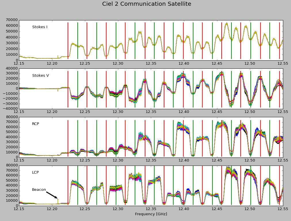
[[File:Linear_to_Circular_Conversion_Figure4.jpg|thumb| | [[File:Linear_to_Circular_Conversion_Figure4.jpg|thumb|400px|Figure 4: Same as Fig. 3, but for all 13 atnennas, with the Stokes I curve for each antenna scaled so that they agree. The beacon frequency in marked in the lower panel.]] | ||
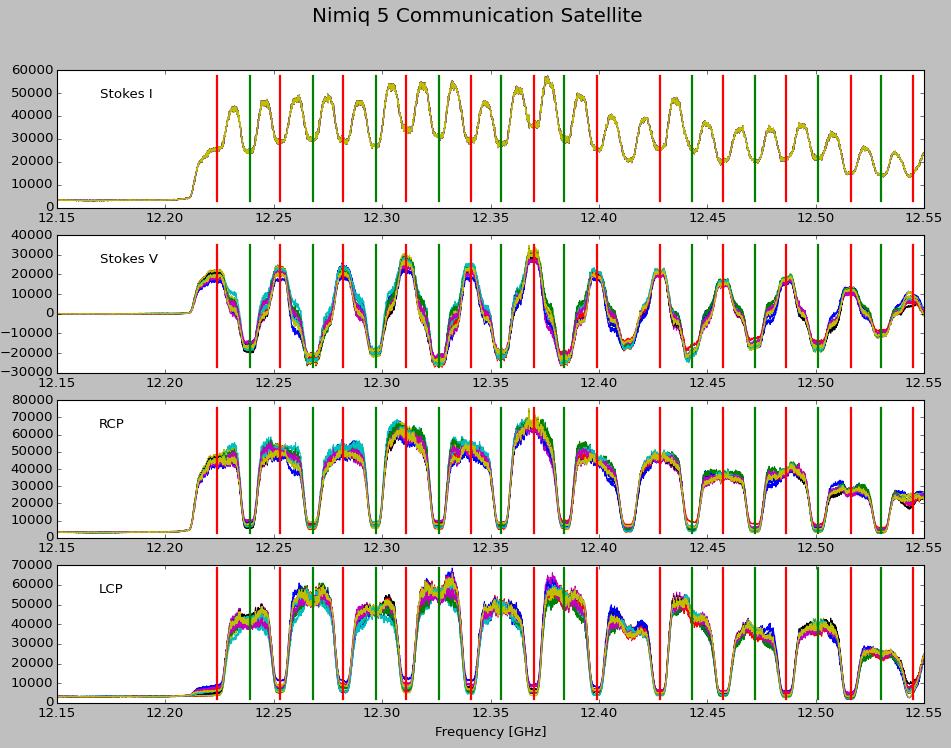
[[File:Linear_to_Circular_Conversion_Figure5.jpg|thumb| | [[File:Linear_to_Circular_Conversion_Figure5.jpg|thumb|400px|Figure 4: Same as Fig. 5, but for the Nimiq-5 commun-ications satellite.]] | ||
At EOVSA’s linear feeds, in the electric field the linear polarization, X and Y, relates to RCP and LCP (R and L) as: | At EOVSA’s linear feeds, in the electric field the linear polarization, X and Y, relates to RCP and LCP (R and L) as: | ||
Revision as of 21:09, 24 September 2016
Linear to Circular Conversion

At EOVSA’s linear feeds, in the electric field the linear polarization, X and Y, relates to RCP and LCP (R and L) as:
In terms of autocorrelation powers, we have the 4 polarization products XX*, YY*, XY* and YX*, where the * denotes complex conjugation. The quantities RR* and LL* are then
One problem is that there is generally a non-zero delay in Y with respect to X. This creates phase slopes in XY* and YX* from which we can determine the delay very accurately. As a check,
For completeness:
When I plot the quantities I, V, R and L as measured (Figure 1) for geosynchronous satellite Ciel-2, the results look reasonable, except that there are parts of the band where R and L are mis-assigned, and others where they do not separate well.
The problem is that residual phase slope of Y with respect to X, caused by a difference in delay between the two channels. This can be seen in the upper panel of Figure 2, which shows the uncorrected phases of XY* and YX*. To correct the phases, the RCP phase was fit by a linear least-squares routine, and then the phases were offset by π/2 for both XY* and YX* according to:
where φ(v) is the phase fit by the linear function. The corrected phases are shown in the lower panel of Figure 2.
When the corrected (primed) quantities are used in
the resulting channel separation is shown in Figure 3, which shows pretty much perfect channel separation, with the correct polarity.
This analysis can be performed on all antennas in a completely automated way, to produce the results of Fig. 3. The curves for each antenna are very similar, except that they show differences in amplitude (gain) as a function of frequency. When the curves are scaled to have the same Stokes I levels, the result is shown in Figure 4. Here the 13 antennas are shown in different colors. It is clear that matching Stokes I also causes an excellent match in the other polarizations. Remaining mismatch is likely due to not subtracting a no-signal background prior to scaling the Stokes I curves.
Also marked in Figure 4 is the location of the beacon signal for Ciel-2, which is at 12.209 GHz. The beacon signal appears in precisely the correct bin (frequency subchannel), indicating that we have precise tuning (certainly not unexpected, but nice to see).
Just to show that the approach is general, the results for a different communications satellite, Nimiq-5, is shown in Figure 5.
Polarization Mixing Correction
Due to relative feed rotation between az-al mounted antennas and equatorial mounted antennas


