Polarization Mixing Correction (Old): Difference between revisions
| Line 108: | Line 108: | ||
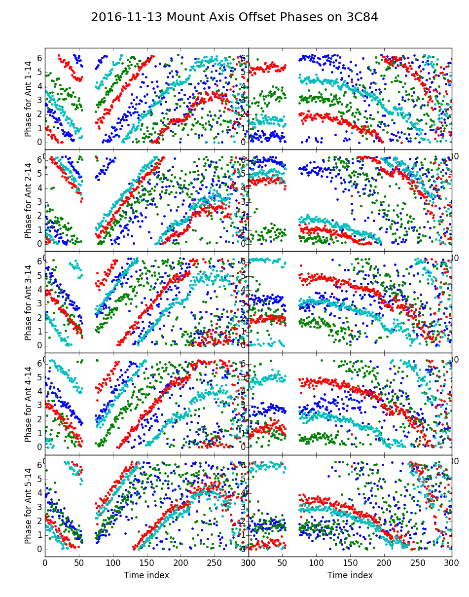
[[File:3C84_cos-el-correction.png|left|thumb|300px|'''Fig. 11:''' Observations and phase-corrected observations for 3C84 taken on 2016-11-13, where d = 15.2 cm was applied. Shown are Ant 1-5 baselines with Ant 14. The remaining phase variations are consistent with a residual Bx baseline error.]] | [[File:3C84_cos-el-correction.png|left|thumb|300px|'''Fig. 11:''' Observations and phase-corrected observations for 3C84 taken on 2016-11-13, where d = 15.2 cm was applied. Shown are Ant 1-5 baselines with Ant 14. The remaining phase variations are consistent with a residual Bx baseline error.]] | ||
On 2016 | On 2016 Nov 13, new observations of 3C84 were taken, and the correction for the axis offset (d = 15.2 cm) were applied, as shown in '''Figure 11''' (at left). It appears that this correction works well, and that there is a residual baseline error on each of the antennas due to the fact that they were originally determined without the axis-offset correction. --[[User:Dgary|Dgary]] ([[User talk:Dgary|talk]]) 14:20, 15 November 2016 (UTC) | ||
Revision as of 16:16, 15 November 2016
Explanation of Polarization Mixing
The newer 2.1-m antennas [Ants 1-8 and 12] have AzEl (azimuth-elevation) mounts (also referred to as AltAz; the terms Altitude and Elevation are used synonymously), which means that their crossed linear feeds have a constant angle relative to the horizon (the axis of rotation being at the zenith). The older 2.1-m antennas [Ants 9-11 and 13], and the 27-m antenna [Ant 14], have Equatorial mounts, which means that their crossed linear feeds have a constant angle with respect to the celestial equator, the axis of rotation being at the north celestial pole. Thus, the celestial coordinate system is tilted by the local co-latitude (complement of the latitude). This tilt results in a relative feed rotation between the 27-m antenna and the AzEl mounts, but not between the 27-m and the older equatorial mounts. This angle is called the "parallactic angle," and is given by:
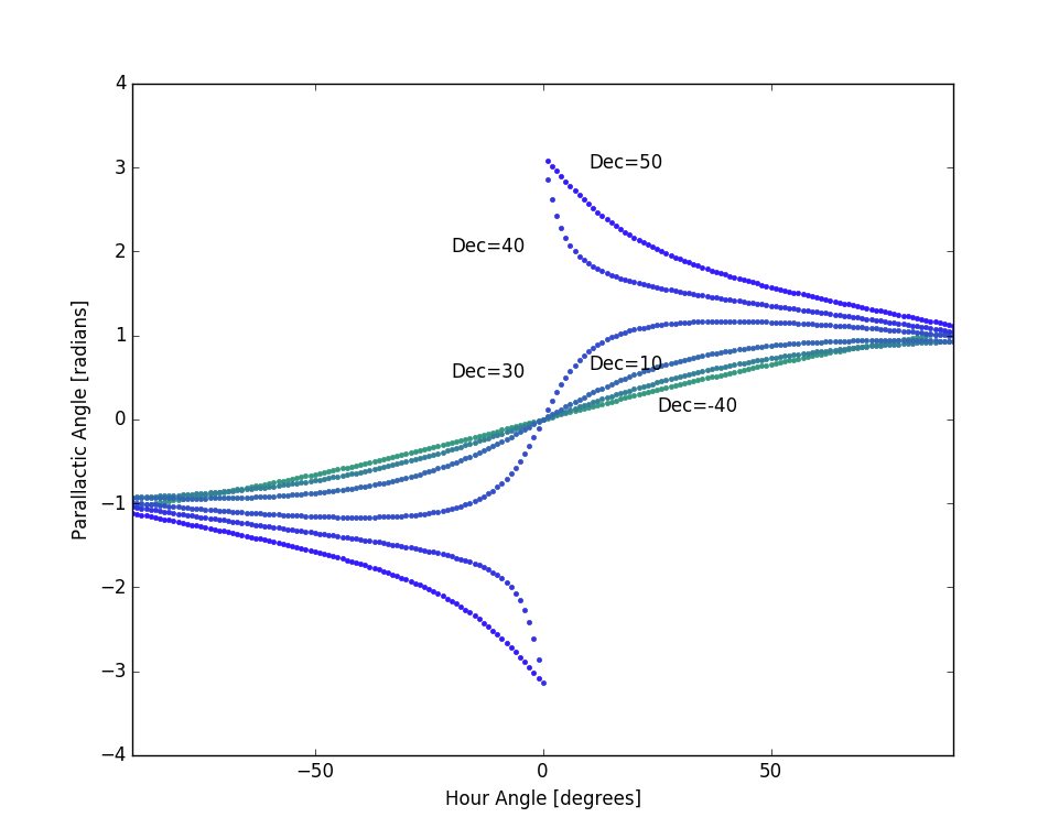
where is the site latitude, is the Azimuth angle [0 north], and is the Elevation angle [0 on horizon]. This function obviously changes with position on the sky, and as we follow a celestial source (e.g. the Sun) across the sky this rotation angle is continuously changing in a surprisingly complex manner as shown in Figure 1. Note that at zero hour angle for declinations less than the local latitude (37.233 degrees at OVRO), but is at higher declinations.
The crossed linear dipole feeds on all antennas are oriented with the X-feed as shown in Figure 2, at 45-degrees from the horizontal, when the antenna is pointed at 0 hour angle. This is the view as seen looking down at the feed from the dish side, although since the feeds are at the prime focus this is the same as the view projected onto the sky. At other positions, the feeds on the AzEl antennas experience a rotation by angle relative to the equatorial antennas.
Because of this rotation, the normal polarization products XX, XY, YX and YY on baselines with dissimilar antennas (one AzEl and the other equatorial) become mixed. The effect of this admixture can be written by the use of Jones matrices (see Hamaker, Bregman & Sault (1996) for a complete description). Consider antenna A whose feed orientation is rotated by , cross-correlated with antenna B with unrotated feed. The corresponding Jones matrices, acting on signal vector are:
and the cross-correlation is found by taking the outer product, i.e.
which relates the output polarization products to the input as
where we have dropped the subscripts and complex conjugate notation for brevity. Of course, there are other effects such as unequal gains and cross-talk between feeds that are also at play, but for now we ignore those and focus only on the effect of this polarization mixing due to the parallactic angle.
Ultimately we mean to apply the inverse of the above matrix to the measured polarization products to recover the unrotated polarization products, but for now we will content ourselves with demonstrating, in the next section, that we have the correct expressions by comparing observations with simulations.
Status of tests
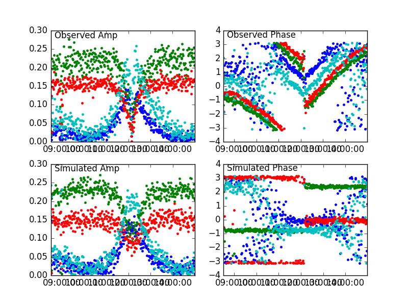
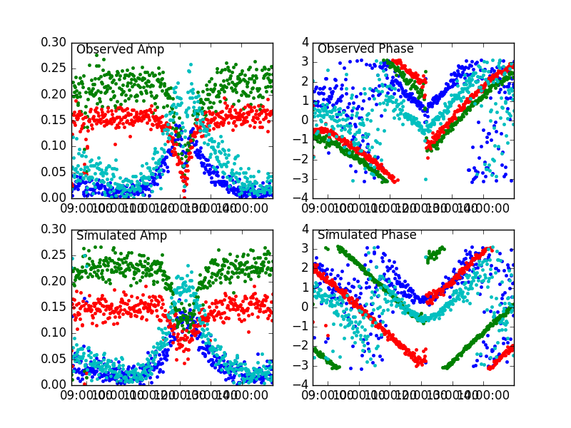
To make the observations, we observe calibrator sources at different declincations over a broad range of hour angle. The two sources observed so far are 3C84, at declination 41 degrees, and 3C273, at declination 2 degrees. We then plot the observed amplitude and phase for each of the observed polarization products [XX, XY, YX, YY]. For this demonstration, we use the baseline of Ant1-14, where Ant1 has the rotating feed and Ant14 has the non-rotating one (with respect to the celestial coordinate system). Figure 3 shows the 3C84 observation and simulation. The upper-left panel is the observed amplitude of the four polarization products during an observation from 08:30-15:00 UT, and the upper-right panel is the corresponding phase. The lower panels are the simulation amplitude and phase, where the simulation assumed constant polarization products with Amp[XX, XY, YX, YY] = [0.15, 0, 0, 0.23], and Phase[XX, XY, YX, YY] = [3.1, 0, 0, 2.4] (radians). A noise level of 0.015 rms was added. It is clear that the amplitude simulation works very well, but the phase does not have the correct character--the only deviation from constant phase is an abrupt 180-degree phase jump in XY and YX at 0 hour angle. Such phase jumps are seen in the observed data, but in addition there is a large amount of phase rotation in the observations that is not in the simulation.
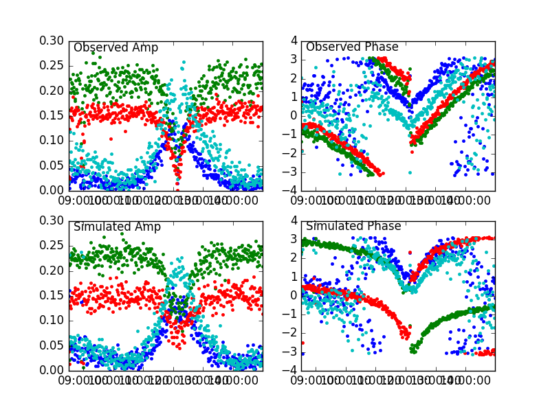
As a test, a simulation was done applying a phase rotation based on , as shown in Figure 4. Applying a rotation by the parallactic angle itself proved to be too small, and did not show the symmetric behavior around 0 hour angle, so the phase rotation applied in Fig. 4 is . It now looks about right, but there is a curvature in the simulation phase that is not really seen in the data.
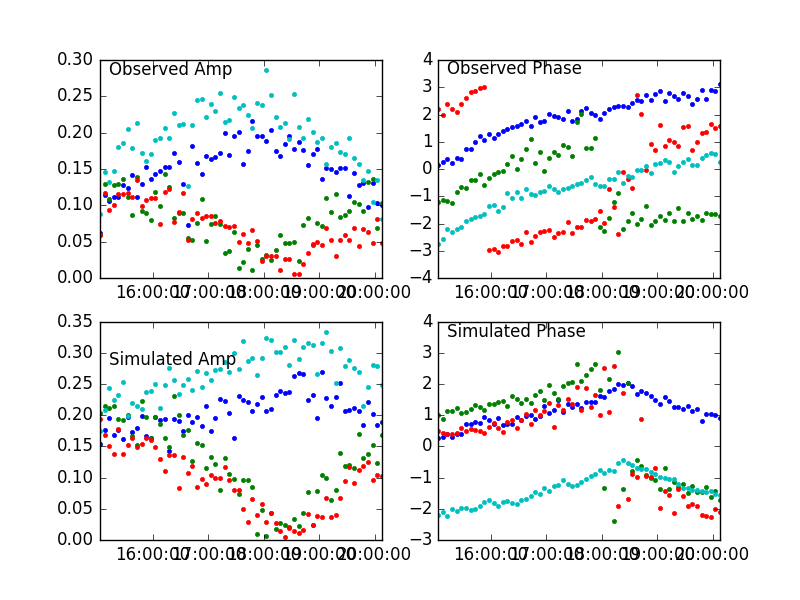
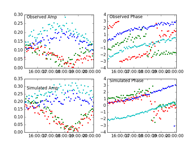
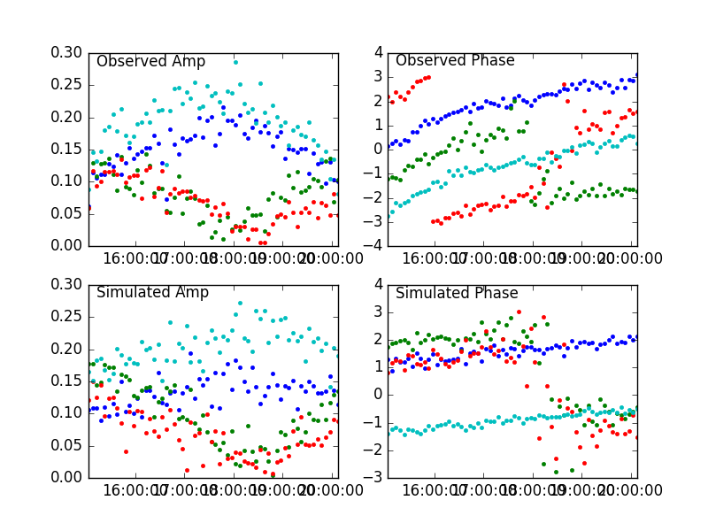
As a check, we repeated the exercise on 3C273, again applying a phase rotation of , with the result shown in Figure 5. As before, the amplitudes match quite well. For this different source, however, the measured phase variation is not symmetric about 0 hour angle, so the simulated phases do not match the observed ones. Finally, we instead apply a phase correction without the absolute value, i.e. just , with the result in Figure 6. Clearly this is "better," but still does not match the phase variation precisely.
Other Possible Reasons for the Observed Phase Variations
It has been suggested that there may be some secular change in phase not related to feed rotation, perhaps a delay error due to a baseline error, or because the Az and El axes do not cross at a common point. However, baseline errors would seem to be unlikely, because exactly the same character in the phase variations occurs on all of the AzEL antennas. And anyway a delay error is ruled out for another reason--the phase variation is not frequency dependent. Figures 7 & 8 illustrate these facts.
Based on these tests, I conclude that the observed phase variations are indeed due to the relative feed rotation, but that something is missing in the above mathematical analysis or its application. One possibility is that there is some subtlety in the complex-conjugation of the Jones matrices, since in the above analysis they are entirely real. --Dgary (talk) 11:50, 22 October 2016 (UTC)
More On Axis Offset
Dr. Avinash Deshpande (Raman Research Institute, Bangalore -- Thanks to Dr. Ananthakrishnan for contacting him) confirms that no phase rotation is expected for the parallactic correction, aside from the 180-degree phase jump at the meridian crossing. He suggests that a non-intersecting axis is more likely, and notes that my plots claiming no evidence of a delay is too hasty. It may be that the small range of frequencies in Figure 8 is too small to see an evident frequency dependence that may nevertheless be there. He notes that the effect of non-intersecting axes is a phase rotation of
where is the elevation angle, and is the offset distance. As a test, I applied this function, using cm (based on the apparent phase variation in the observed phases), and obtained the results in Figures 9 and 10. Although the observed phases show a bit more curvature than the simulation, this can be due to residual baseline errors, so I think it is fair to say this is a promising result. We can prove this very shortly, since the feed rotator on the 27-m antenna is soon to be working (I hope). The prediction is that rotating the 27-m feed to keep it parallel to the 2.1-m feeds on these antennas will correct the amplitudes, but the phases will still show the same behavior (since they are due to a different cause), and also that using a wider range of frequencies (which we can do, especially now that the high-frequency receiver is available) will show a frequency dependence in the amount of phase variation. --Dgary (talk) 04:55, 8 November 2016 (UTC)
Further update
On 2016 Nov 13, new observations of 3C84 were taken, and the correction for the axis offset (d = 15.2 cm) were applied, as shown in Figure 11 (at left). It appears that this correction works well, and that there is a residual baseline error on each of the antennas due to the fact that they were originally determined without the axis-offset correction. --Dgary (talk) 14:20, 15 November 2016 (UTC)


![{\displaystyle {\boldsymbol {e}}_{in}=[X,Y]}](https://wikimedia.org/api/rest_v1/media/math/render/svg/bc4eeebe0b92120f842f54a160b57734dc5f6b5e)


