Obtaining u,v,w From An Antenna Array
A synthesis imaging radio instrument consists of a number of radio elements (radio dishes, dipoles, or other collectors of radio emission), which represent measurement points in u,v,w space. We need to describe how to convert an array of dishes on the ground to a set of points in u,v,w space.
E, N, U coordinates to x, y, z
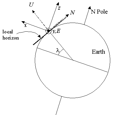
The first step is to determine a consistent coordinate system. Antennas are typically measured in units such as meters along the ground. We will use a right-handed coordinate system of East, North, and Up (E, N, U). These coordinates are relative to the local horizon, however, and will change depending on where we are on the spherical Earth. It is convenient in astronomy to use a coordinate system aligned with the Earth's rotational axis, for which we will use coordinates (x, y, z) as shown in Figure 1. Conversion from (E, N, U) to (x, y, z) is done via a simple rotation matrix:

Fig. 1: The relationship between
E, N, U coordinates and
x, y, z coordinates, for a latitude

. The direction of
z is parallel to the direction to the celestial pole. The directions
y and
E are the same direction.

which yields the relations:

Baselines and Spatial Frequencies
Note that the baselines are differences of coordinates, i.e. for the baseline between two antennas we have a vector:

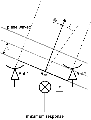
Fig. 2: Geometry of an interferometer baseline where a delay

is inserted in one antenna, in order to steer the phase center to a direction

from the vertical

.

This vector difference in positions can point in any direction in space, but the part of the baseline that matters in calculating u,v,w is the component perpendicular to the direction  (the phase center direction), which we called
  in Figure 2. Let us express the phase center direction as a unit vector
 , where
  is the hour angle (relative to the local meridian) and
  is the declination (relative to the celestial equator). Then
  .
.
Recall that the spatial frequencies u,v,w are just the distances expressed in wavelength units, so we can get the u,v,w coordinates from the baseline length expressed in wavelength units from the following coordinate transformation (see Thompson 1999 for details):


How baseline errors can contribute to the error in phase
The geometric phase difference at the phase center ( term in (1)) is:
![{\displaystyle \phi _{g}=2\pi \tau _{g}\nu =(2\pi /\lambda )[B_{x}\cos \delta _{o}\cos h_{o}-B_{y}\cos \delta _{o}\sin h_{o}+B_{z}\sin \delta _{o}]}](https://wikimedia.org/api/rest_v1/media/math/render/svg/2b74473ae701f4c967fd59333b0fcfa3988aea64)
where  , geometric delay. We can see what can affect the geometric phase by taking the differential of this expression:
![{\displaystyle {\begin{aligned}d\phi _{g}=2\pi \nu d\tau _{g}=(2\pi /\lambda )[&dB_{x}\cos \delta _{o}\cos h_{o}-dB_{y}\cos \delta _{o}\sin h_{o}+dB_{z}\sin \delta _{o}\\+\ &d\alpha _{o}\cos \delta _{o}(B_{x}\sin h_{o}+B_{y}\cos h_{o})\\+\ &d\delta _{o}(-B_{x}\cos h_{o}\sin \delta _{o}+B_{y}\sin h_{o}\sin \delta _{o}+B_{z}\cos \delta _{o})]\end{aligned}}}](https://wikimedia.org/api/rest_v1/media/math/render/svg/210ab11a3cb2bcba431a38f77cca793fe73fe3ab)

where we have used the relation between right ascension and hour angle:  , so
, so  . Equation (2) shows how baseline errors
  and source position errors (
 ,
,  ) will affect the error in group delay
  (or yield an error in phase
  ). Note that a clock error is equivalent to a source position error
  .
.
If we have a source whose position is known, we can use Equation (2) to find the location of the antennas (this is called baseline determination). The error in antenna position is largely independent of the baseline lengths. For example, say that we can measure  to within 1 degree at 5 GHz (
 = 6 cm). Then we can measure
  ,
,  and
and  to a precision of order (1 / 360) 6 cm ~ 1 / 60 cm even though
  = 5000 km or more (VLBI).
The time of day and location of the antennas must be known to relatively high accuracy -- needed for determining the geometric delay. A clock error of 1 s, or a baseline error of a few cm, will cause a serious phase shift of the source over, say, 10 minutes. At OVRO, using a GPS clock and measuring baselines with cosmic source calibration, we get a time accuracy of << 1 ms, and baseline errors of about 3 mm. Therefore, these effects are not serious over a short time interval, but may still be problematic over 8 hours. This is one reason that we do phase calibration observations every ~ 2 hours.


![{\displaystyle \phi _{g}=2\pi \tau _{g}\nu =(2\pi /\lambda )[B_{x}\cos \delta _{o}\cos h_{o}-B_{y}\cos \delta _{o}\sin h_{o}+B_{z}\sin \delta _{o}]}](https://wikimedia.org/api/rest_v1/media/math/render/svg/2b74473ae701f4c967fd59333b0fcfa3988aea64)

![{\displaystyle {\begin{aligned}d\phi _{g}=2\pi \nu d\tau _{g}=(2\pi /\lambda )[&dB_{x}\cos \delta _{o}\cos h_{o}-dB_{y}\cos \delta _{o}\sin h_{o}+dB_{z}\sin \delta _{o}\\+\ &d\alpha _{o}\cos \delta _{o}(B_{x}\sin h_{o}+B_{y}\cos h_{o})\\+\ &d\delta _{o}(-B_{x}\cos h_{o}\sin \delta _{o}+B_{y}\sin h_{o}\sin \delta _{o}+B_{z}\cos \delta _{o})]\end{aligned}}}](https://wikimedia.org/api/rest_v1/media/math/render/svg/210ab11a3cb2bcba431a38f77cca793fe73fe3ab)


