About Instrument
Summary
| OVSA Expansion Project Instrument |
|
Antennas
27-m Antennas for Calibration: The two existing 27-m antennas will be refurbished with new control systems and installation of a cryogenic system for He-cooled receiver operation (system temperature about 15 K). This will permit phase calibration in 90 s on sources as weak as 0.5 Jy. It also enables the suite of night-time science described on the science page.
27-m antennas, to be used for precision calibration (and night-time science).
2-m Antennas for Solar Observations: The work-horses of the array will be the thirteen 2-m antennas. These precision antennas will see the entire disk of the Sun and track with high accuracy for stable operation. Eight new antennas will be installed, and the five existing antennas will be upgraded with new control systems and reflectors, to be compatible with the new antennas. The complexity of the system attached to the antennas will be greatly simplified (see technology page). All antennas will be equipped with dual-polarization feeds for simultaneous right-hand and left-hand circular polarization measurements. The photo at right is a previous design for the Korean Solar Radio Burst Locator. Click here for drawings of the new design.
2-m antennas: the work-horses of the array.
Array Configuration
Three-Armed Spiral Configuration: The imaging properties of the instrument (image quality, resolution, snapshot vs. rotational synthesis properties) are entirely determined by the array configuration. The original plan was for a 3-armed spiral, but environmental concerns required a shift of the inner antennas. The inner antennas still follow a spiral, but the outer antennas follow a different spiral. The overall dimensions of the array are 1.08 km EW by 1.22 km NS, yielding a resolution (a sythesized beam width) of about 50"/n GHz. To put this in perspective, at the 17 GHz frequency of the Nobeyama Radioheliograph, the resolution is about 3" (5 times better than Nobeyama).
Layout of inner 9 antennas of the array, showing the break in spiral pattern due to environmental concerns.
New Control Building: In addition to the antennas, a new control building will be built to house the environmentally controlled signal processing room, the central instrument control room, and the data storage and pipeline facility.
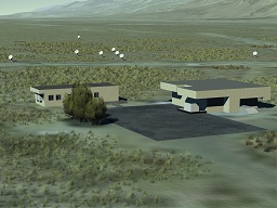
View of the inner part of the array, with the new control building in the foregound (Artist's conception. Credit: Isaac Gary). Click for larger version.
Frequency Range, Bandwidth and Resolution
Frequency Range: The overall frequency range is 1-18 GHz, which is an industry standard that is well suited to the most interesting part of the solar radio spectrum in the case of both active regions and the microwave component of flares.
Bandwidth: The instantaneous bandwidth of the system is 500 MHz, which allows the 1-18 GHz range to be sampled in 34 "tunings." These 500 MHz channels can be selected in any order (frequency agile) and data sampled on a 20 ms cadence.
CASPER Roach board provides the narrow band frequency channels (122 kHz) for RFI excision. The real-time data pipeline will integrate to science resolution.
Frequency Resolution: The instrumental resolution is 122 kHz, which is necessary for optimal excision of radio frequency interference (see technology page). However, this is much finer resolution than required for the science drivers, and would yield far too much data. Instead, these fine frequency channels will be combined in a frequency-dependent way to provide 1 MHz resolution at the lowest frequencies near 1 GHz and increase to about 50 MHz resolution near 18 GHz.
Example solar bursts observed with the FASR Subsystem Testbed at 20 ms time resolution and 1 MHz frequency resolution. This matches the resolutions of the OVSA Expansion, which will provide imaging on this time and frequency resolution.
Time Resolution for Bursts: Solar radio bursts must be imaged using "snapshot" mode, because there is no time to employ the technique of Earth-rotation synthesis to improve imaging. We can, however, use limited frequency synthesis to improve image quality at the expense of frequency resolution. This trade-off is made offline using the recorded data. The time resolution for a single 500 MHz band is 20 ms, and it takes 0.68 s to cover the entire 1-18 GHz frequency range. See the science page for imaging example. However, it is possible to use the frequency-agility of the instrument to trade off frequency coverage for time resolution.
Snapshot UV coverage for bursts, utilizing 20% frequency synthesis. The image quality is a direct function of the density of points in this diagram.
Time Resolution for Full Sun Imaging: For more slowly varying sources such as active regions of the quiet solar disk, Earth-rotation synthesis and frequency synthesis can both be employed. Typically, active regions (see science page) can be imaged well at half-hour resolution, while weaker quiet Sun sources (plage regions, prominences and filaments) can be imaged on a 4 hour timescale (see science page).
Earth-rotation synthesis UV coverage for active regions and other features, utilizing 20% frequency synthesis.