About Construction
EOVSA Construction
This is a video of the EOVSA Subsystem Testbed (EST) recording data from a GPS satellite. The GPS signal amplitude on three baselines is shown in the three upper panels, and the phase (radians) is shown in the middle three panels. The bottom panel shows the phase closure. The phases sweep through a range of 2p every few seconds as the satellite moves through the interferometer fringes.
Posted by Dale Gary, Jan 19, 2012. Click on the picture to play the video (4.8 MB).
Layout
Final layout of the array as now being built. Here you will see the locations of each of the 13 2-m antennas (1-13) and the two 27-m antennas (A and B), as well as the new building (the southeast corner is marked SE Bldg). The trench lines are shown following existing roads as much as possible. New roads have been constructed in the areas shown with thin outlines. These are drawn on the Google map of the site.

Layout of the array, now under construction.
Surveying for the Antenna Locations
Kjell Nelin, Site Manager, surveying for the locations of the antennas. The layout of the antennas was determined first by GPS, then surveyed with reference to the existing "T" layout of the old mm-array (visible to the right in the Google map, above).
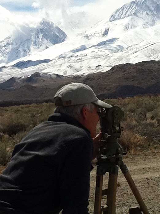
The surveying of antennas locations took place in Spring 2011. Click for larger image.
Start of Construction, 2011 Sept. 14
Ground Breaking: After more than one year of environmental assessments (May 2010-Aug 2011), cultural and biological surveys, obtaining various permits, legal documents, and other requirements, actual construction began with ground-breaking on 2011 Sept. 14 for road construction. The array construction work consists of four phases: 1. Road building, 2. trenching and conduit, 3. concrete work for antenna pads, and 4. fencing around the pads, while additional work is needed to install a new building.

Photo taken 2011 September 14, at the first ground-breaking for the project. Click for larger image.
Conduit
More than 20,000 feet of PVC conduit is needed for the optical fiber transmission system: Dale Gary is shown here standing among the stacks of PVC conduit. This conduit will be buried during the trenching phase of construction, slated to begin 2011 October 3. This photo was taken 2011 August 19.
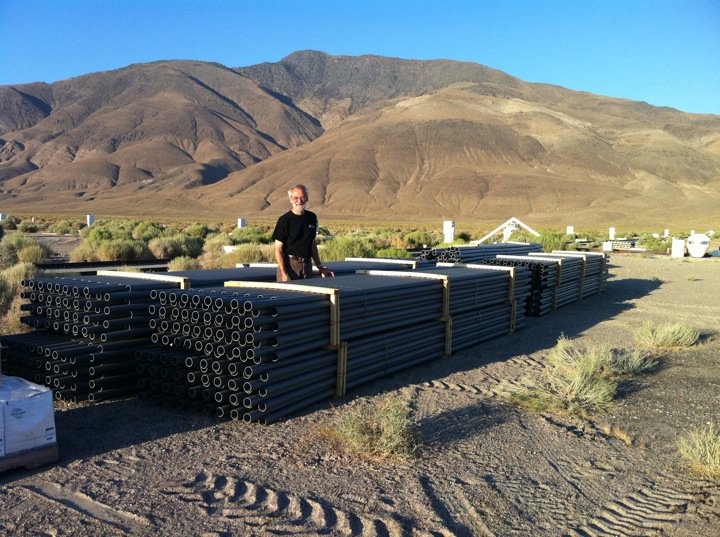
More than 20,000 feet of PVC conduit has been delivered to the site, for burial during the trenching phase (phase 2 of construction). Click for larger image.
Archaeological Monitoring
Mitigation for potential disturbance of cultural artifacts: As a result of the environmental assessments for the project, some parts of the site require mitigation in the form of monitoring of the work by an archaeologist and a tribal monitor from the Big Pine Paiute Tribe. This photo shows the area around the site of the new building, being checked on 2011 September 15. No substantial cultural artifacts were found.
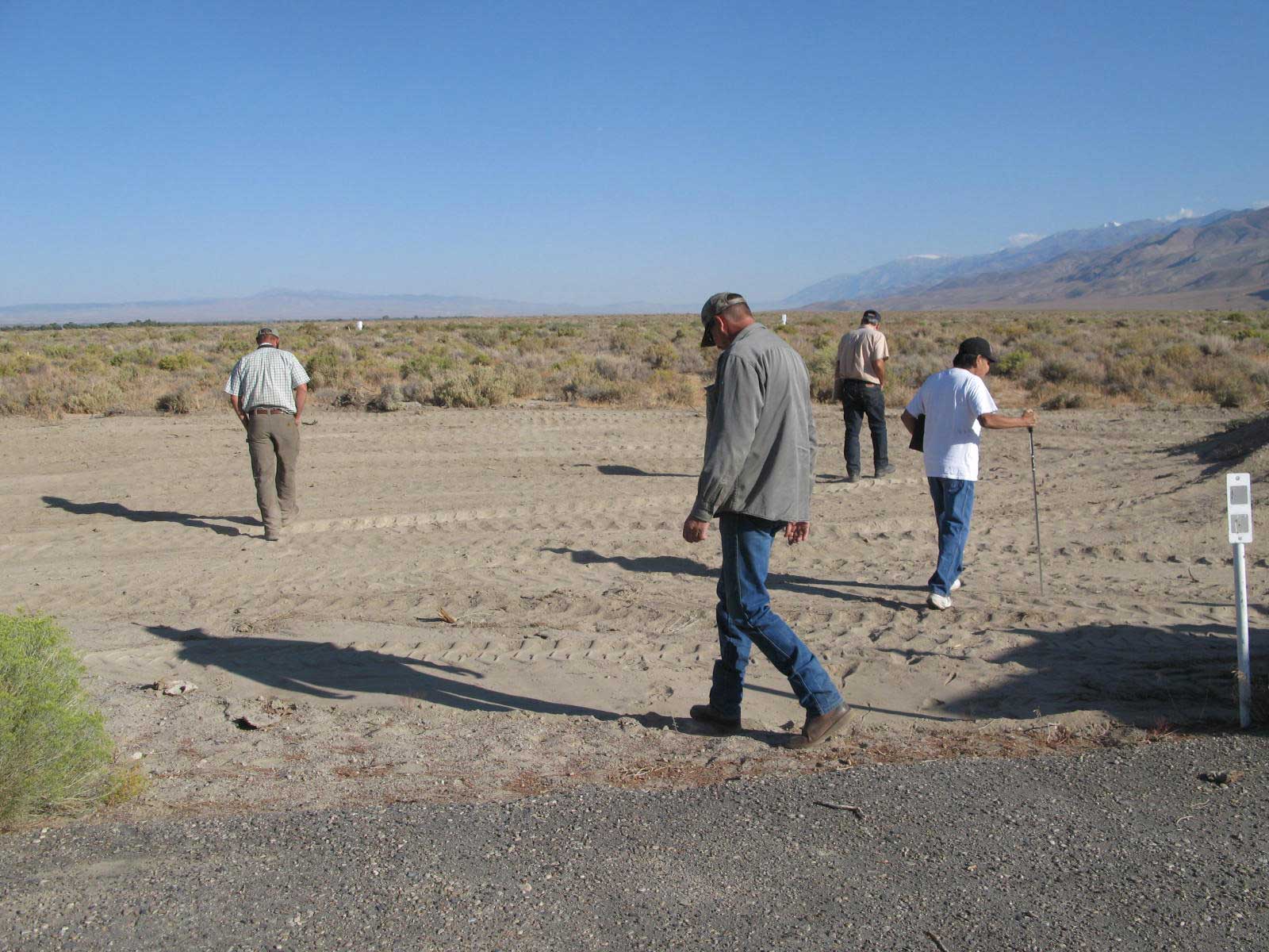
The archaeologist, tribal monitor, and others surveying the wrok to ensure environmental compliance. Click for larger image..
Roads
An example of a stretch of new road through the desert: This is a view of the new road looking southwest from the site of antenna 10 back toward the array center (see array layout). This photo was taken 2011 September 15.
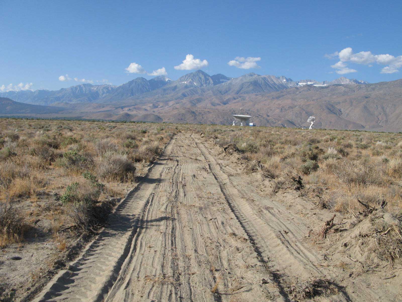
The road from antenna 10 looking back toward the array center. Click for larger image.
Trenching
Start of trenching for the cable runs: This is a view of the open trench with one run of conduit inside, looking east from antenna A (one of the 27-m antennas). One of the Hubble pull boxes is seen in the foreground. The trench will be filled in again once all of the conduit is installed. Some portion of the trench will have as many as 6 conduits. This photo was taken 2011 October 03. Trenching was completed about three weeks later.
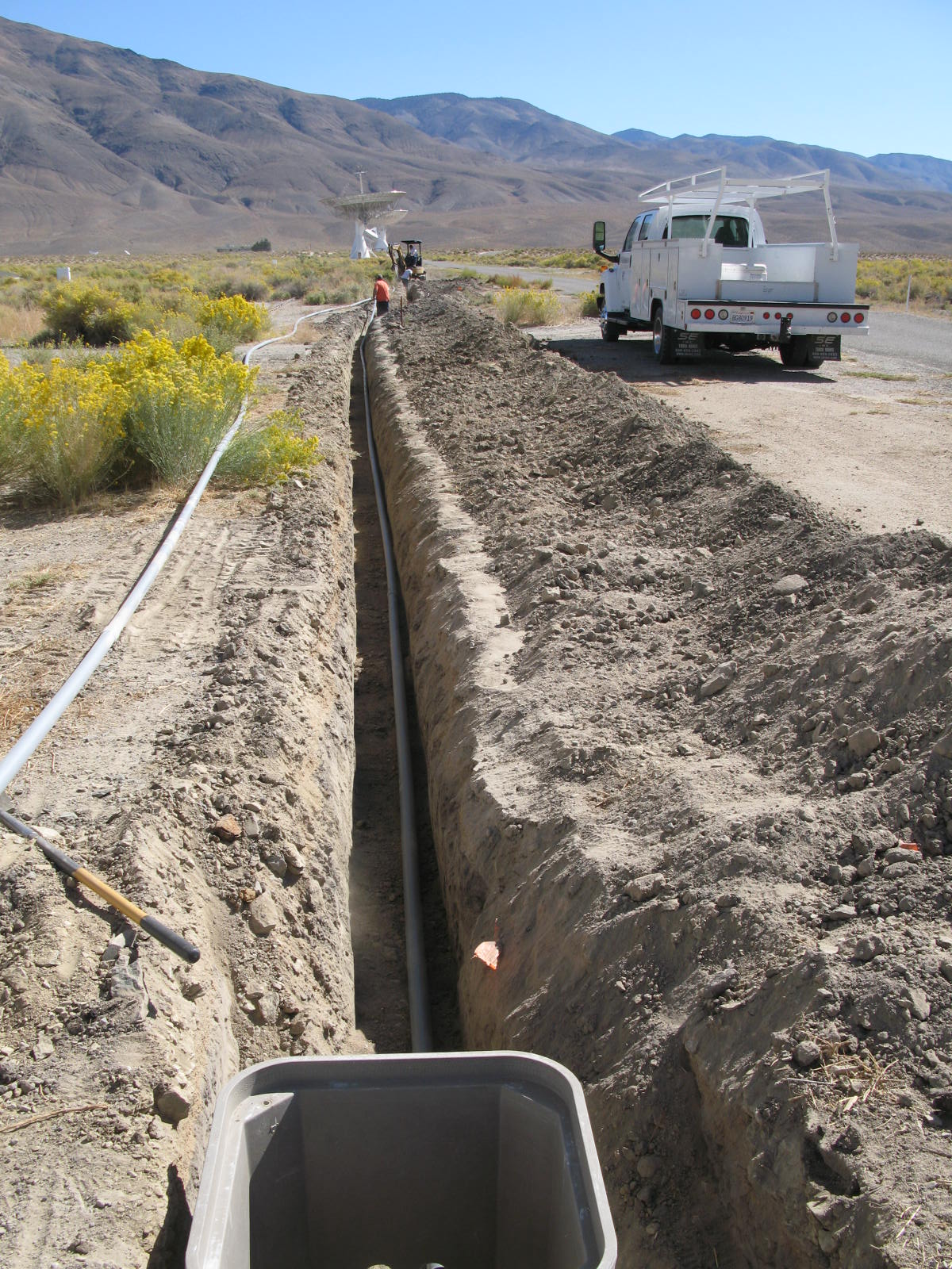
The open trench looking east from antenna A. Click for larger image.
Antenna Pads
Start of concrete work for the antenna pads: Each 2.1 m antenna sits on a 16 ft x 16 ft concrete pad, with a total of 13 to be constructed. Work began 2011 Nov. 1, and was completed 2 weeks later. This photo was taken 2011 November 01.
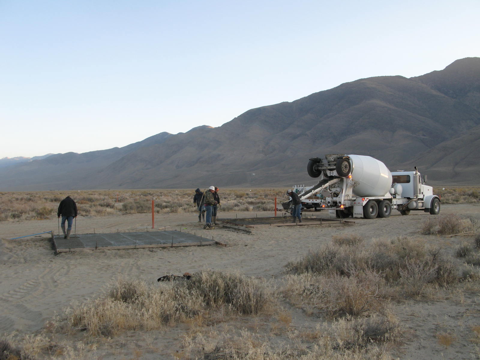
Pouring concrete for the antenna pads. Click for larger image.
Central Array
The array takes shape: This photo of the central array was taken from the platform on the 40 m telescope at OVRO, to provide a viewpoint with some height. The photo was taken 2012 October 26. Click here for a somewhat closer look. Click here for a "roll-over" of the array center during construction, with and without annotation, taken 2011 November 07. A similar view is available (here) showing the completed pads and fencing, with Antenna 1 installed as of 2011 December 23.
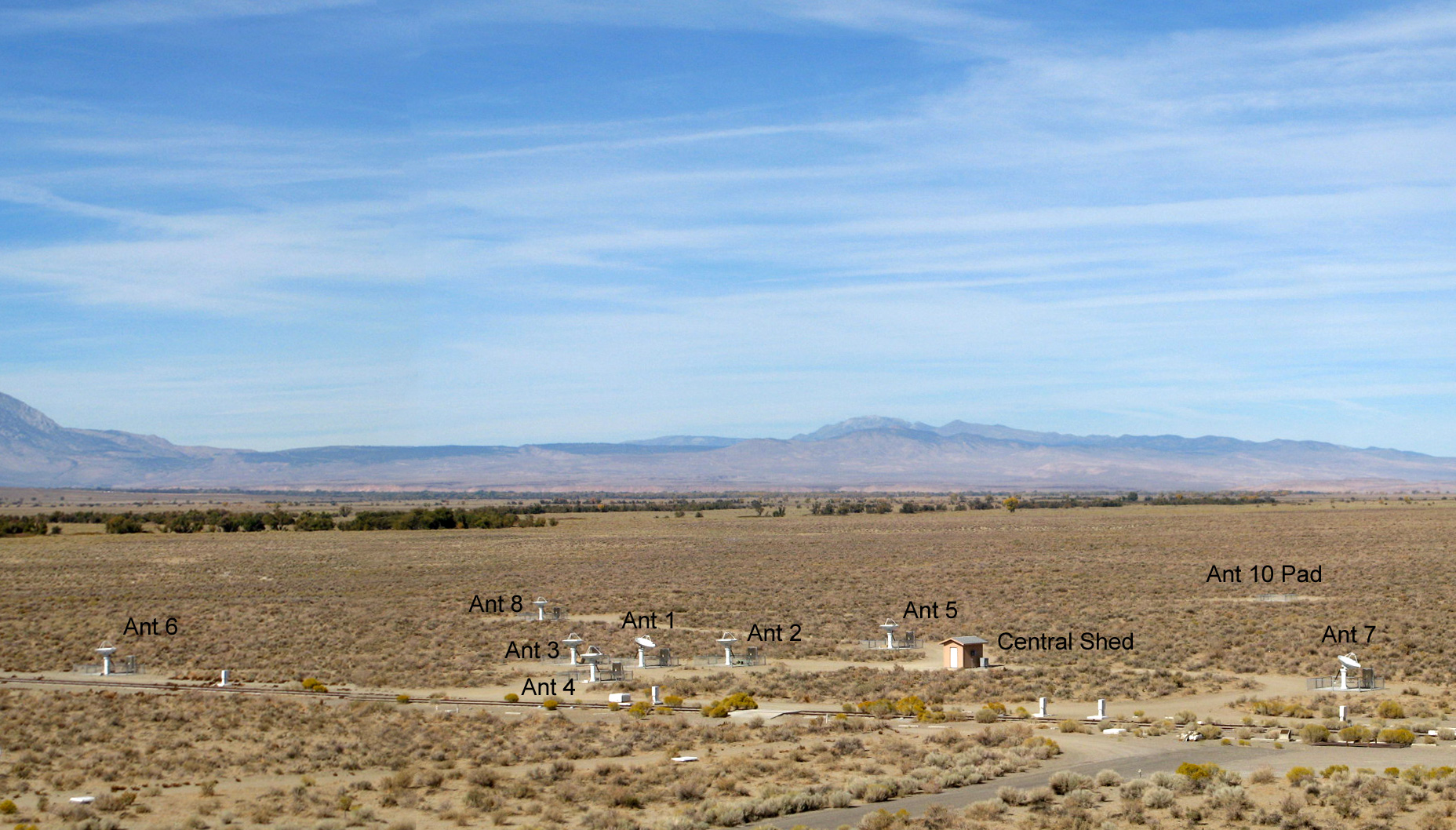
Panoramic view of the antenna at the array center. Click for a "roll-over" image.
Central Shed
The shed for the array center: The signals from the denser concentration of 2.1 m antennas near the array center are collected at the "breakout shed" for transmission to the control building. The power from the central power transformer also fans out from here to the individual antennas. This photo was taken 2011 November 23.
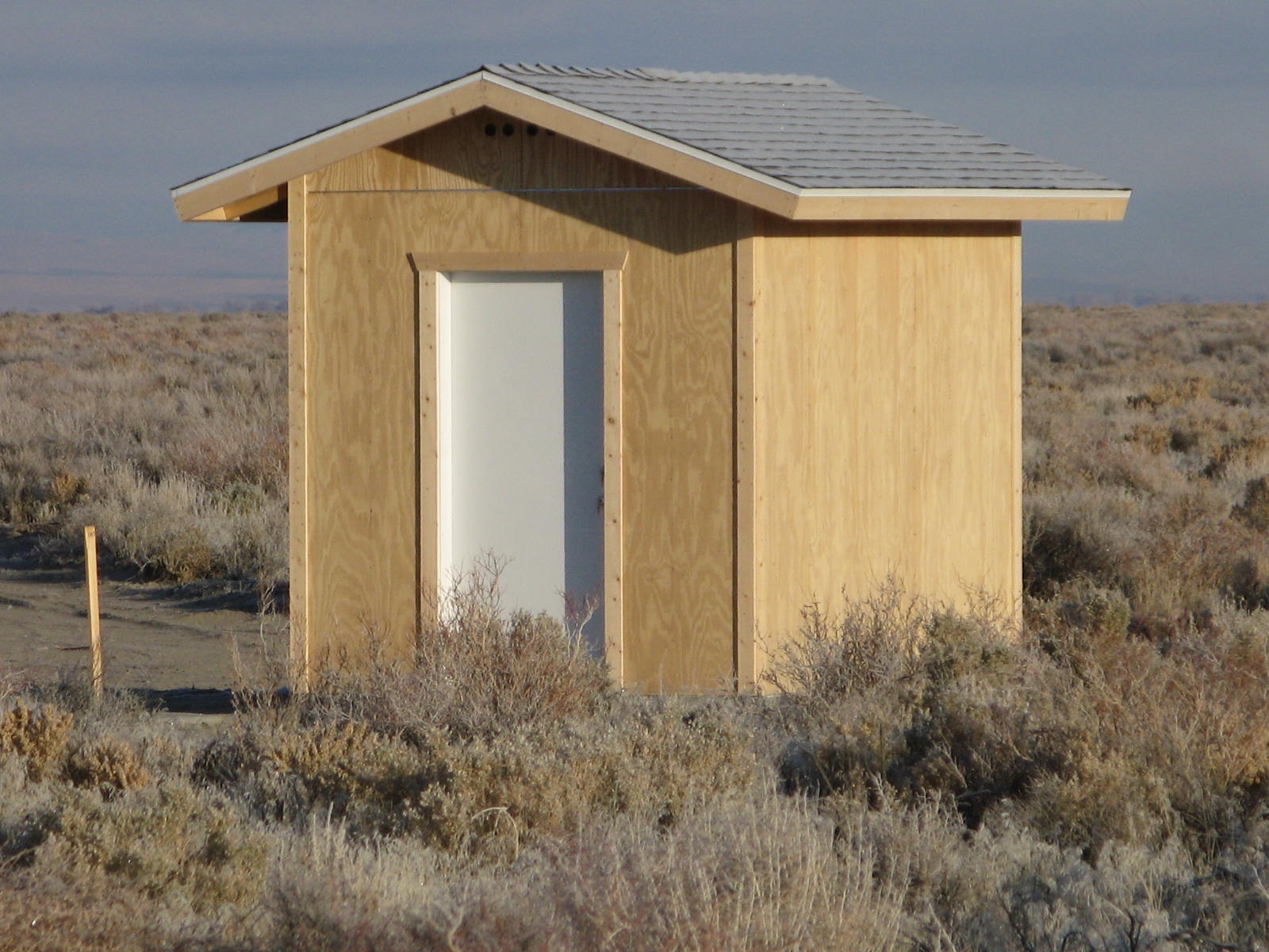
Breakout shed near the array center, where signals from the individual antennas come together for transmission to the control building. It will be painted shortly. Click for larger image.
Fencing
Fencing around the antenna pads: Each of the antennas requires a fence to keep the marauding cows from scratching their backs on the antennas. This photo of the inner array shows two pads and the shed. The fencing was completed 2011 December 09, the date this photo was taken.

Fencing around two of the antenna pads, with breakout shed. Click for larger image.
Antennas
First delivery of 2.1 m Antennas: The first two 2.1 m antennas, built by InterTronic Solutions and Viking Satcom, were delivered on 2011 December 01. The first one (actually Antenna 2), pictured here, was assembled on 2011 December 08 on an older, existing concrete pad because it is already wired to the old control room. Pointing tests began first week in January 2012. This photo was was taken 2011 December 09. We have taken delivery of all eight of the new antennas, and they have been erected at their central array locations during fall 2012 (see Central Array, above).
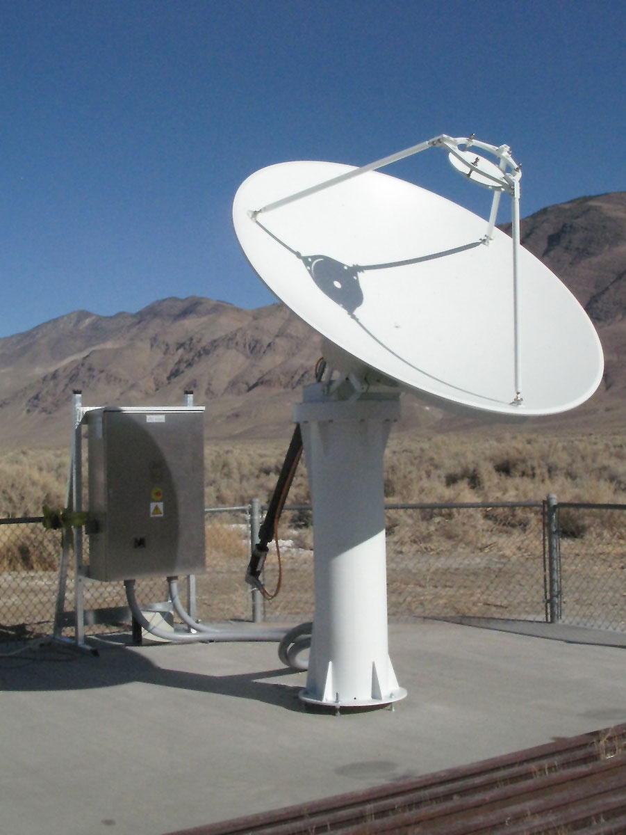
The first of the new 2.1 m antennas, with controller in the box in the background. Click for larger image.
Antenna 1
Antenna 1 installed on its pad: The first antenna has been installed on its concrete pad. This photo was taken 2011 December 23. A wide view showing the nearby (then empty) pads is available. Click here.
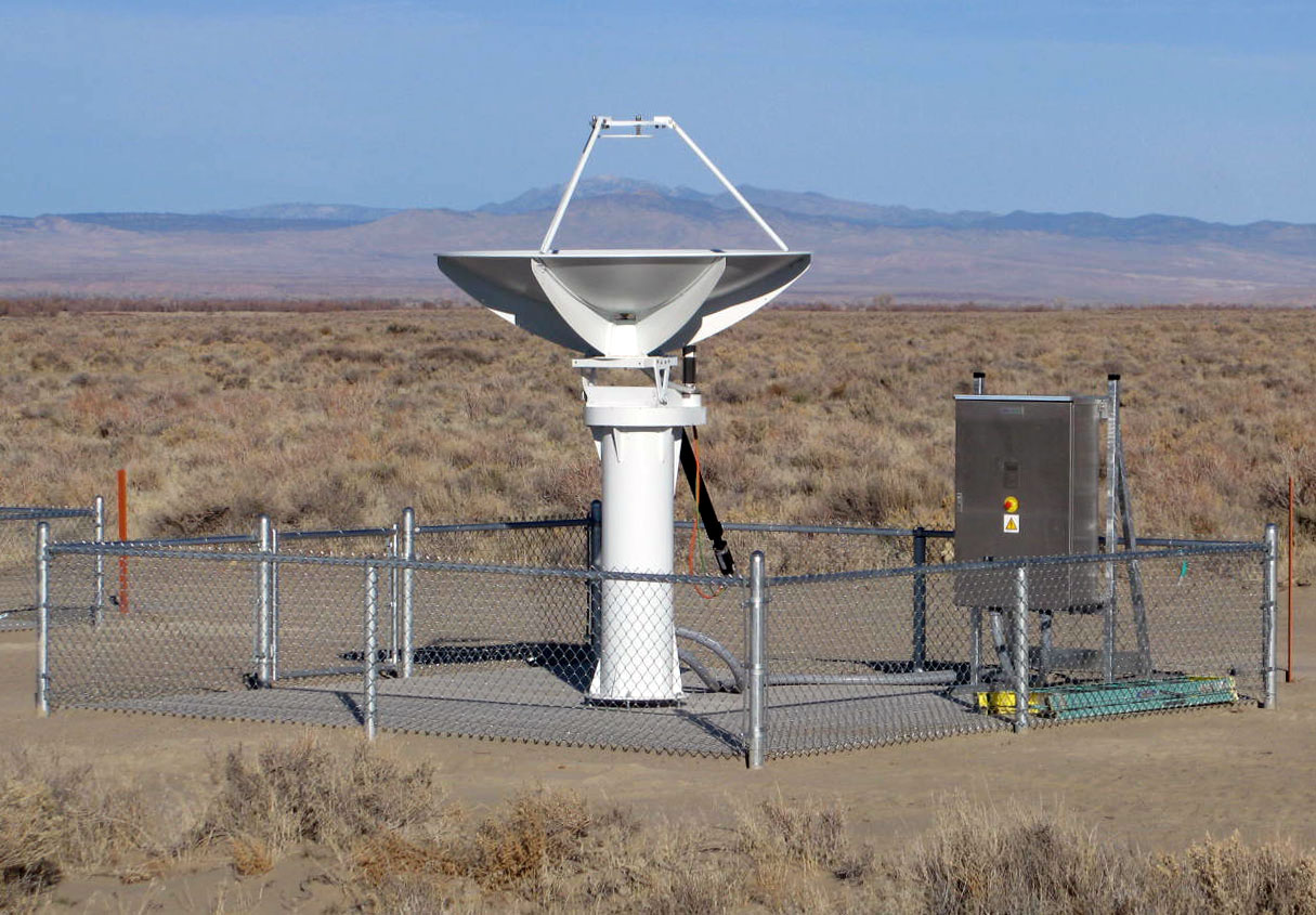
The first antenna to be erected permanently on its designated pad, at the center of the array. Click for larger image.
27-m Antenna Refurbishment
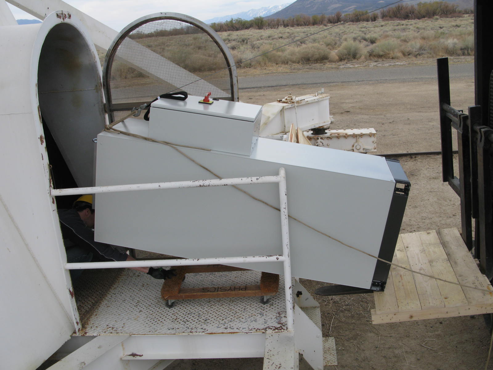
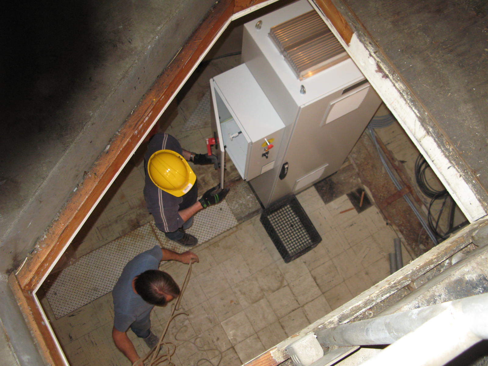
27-m antenna controllers installed: The two 27-m antennas, which will be used for calibration and night-time science, are being thoroughly refurbished with all new wiring and new control systems. The control systems arrived on 2012 April 03, and have been installed along with new motors and encoders. Other images are available (in through the doorway) and (all installed). We completed a thorough suite of non-destructive testing of the backing structure of the antennas in August 2012, and are pleased to learn that the structure is sound, except for a few places where some corrosion had occurred. These spots have been repaired with welded patches.
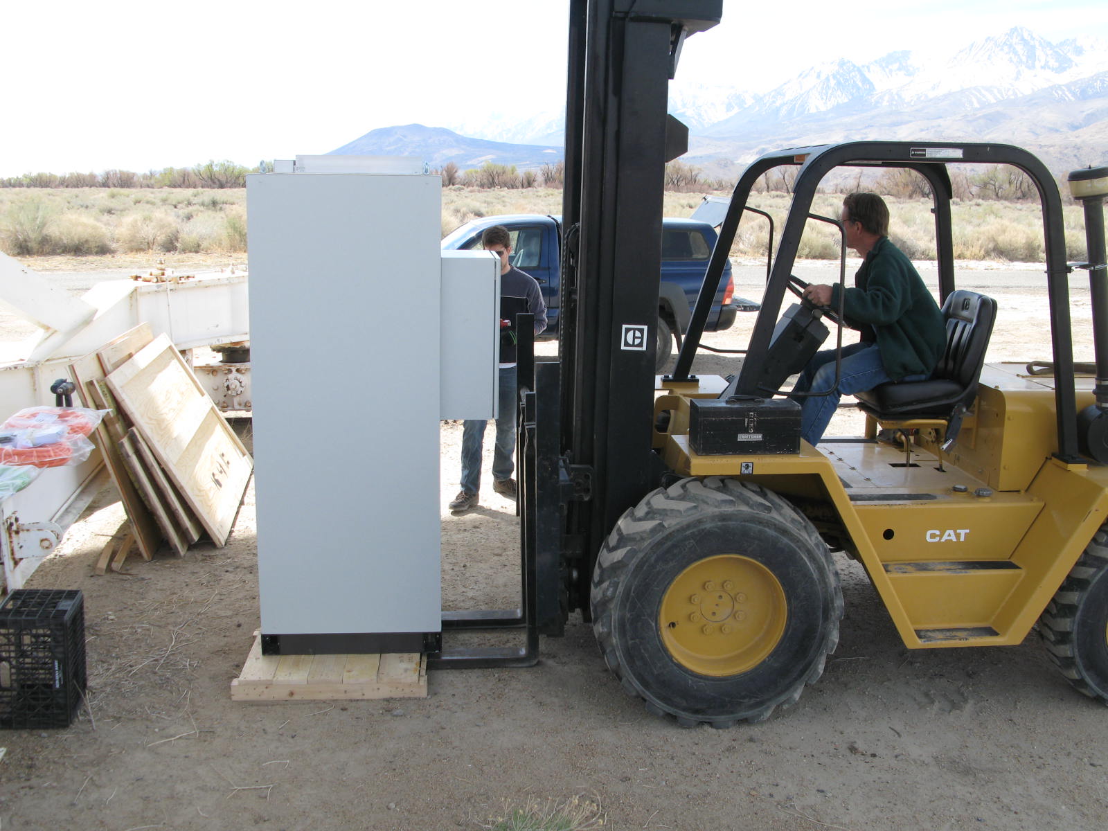
the new 27-m antenna controllers, being readied for installation in Antenna A. Click for larger image.
New Control Building
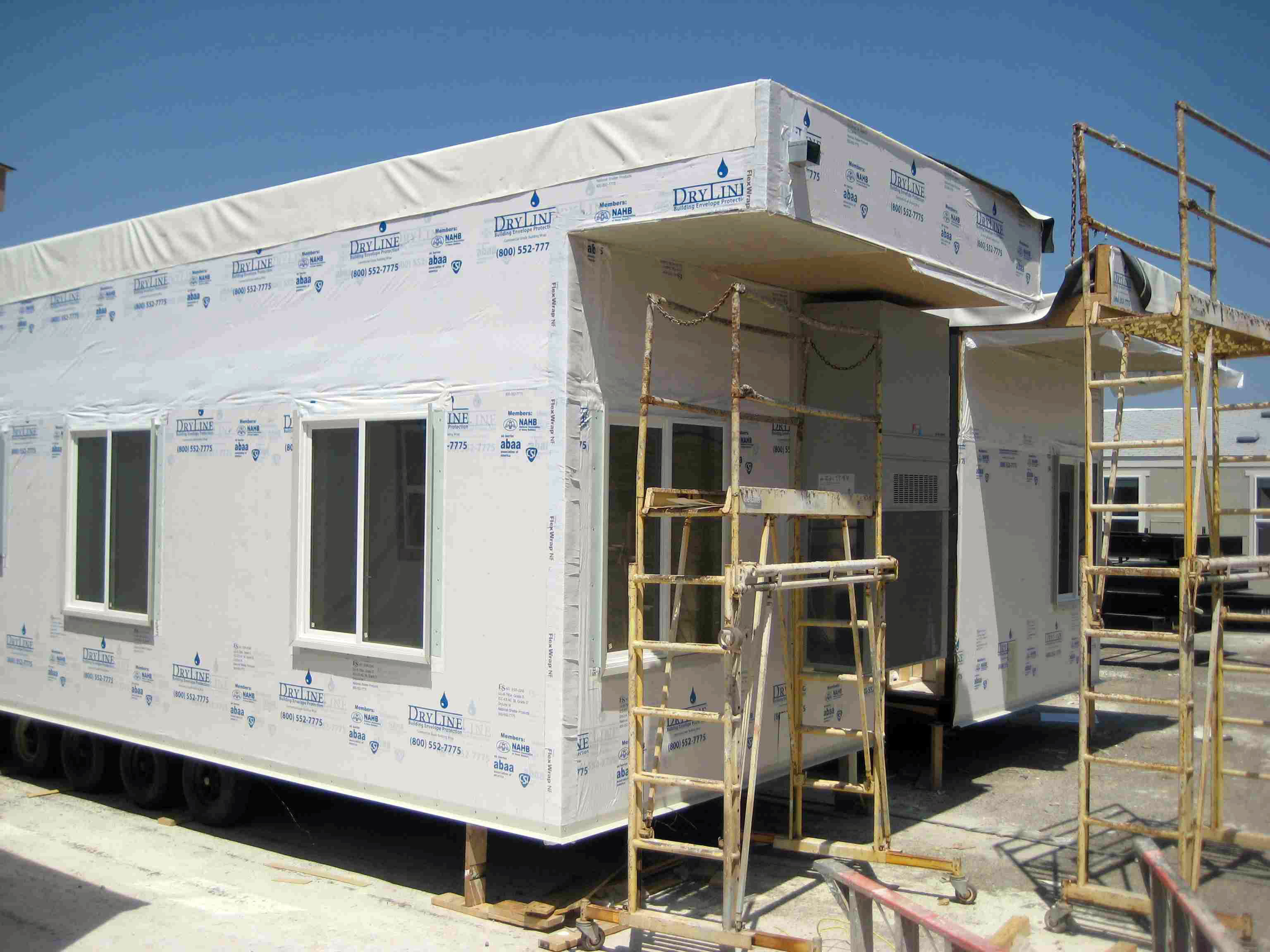
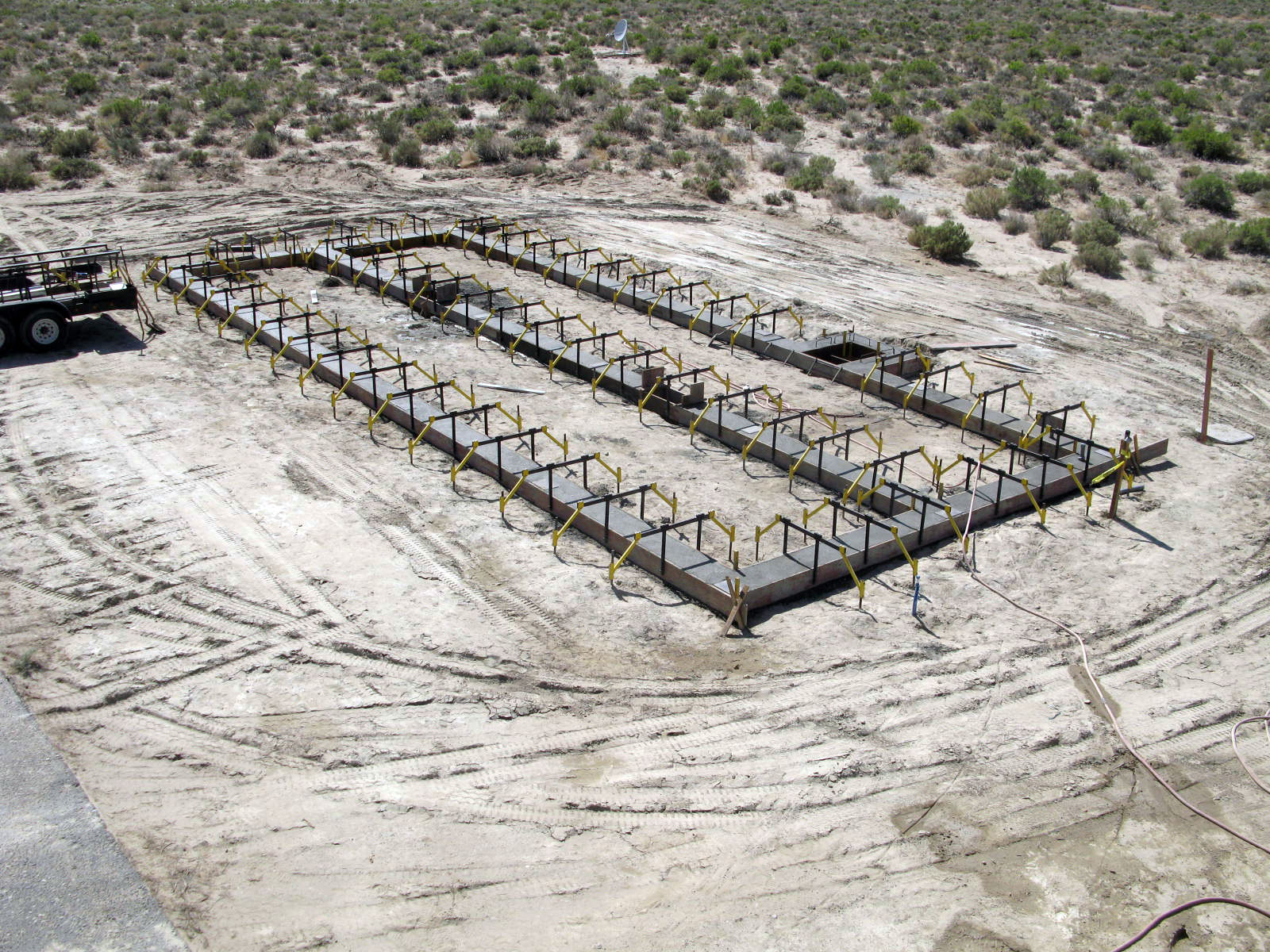
Control Central: The new array requires a brand-new control building, which is a factory built 24 x 60 modular building on a custom foundation. The building is now complete, and we are all moved in! Other images taken during construction are available (At the factory), (Foundation), and (Some Assembly Required).
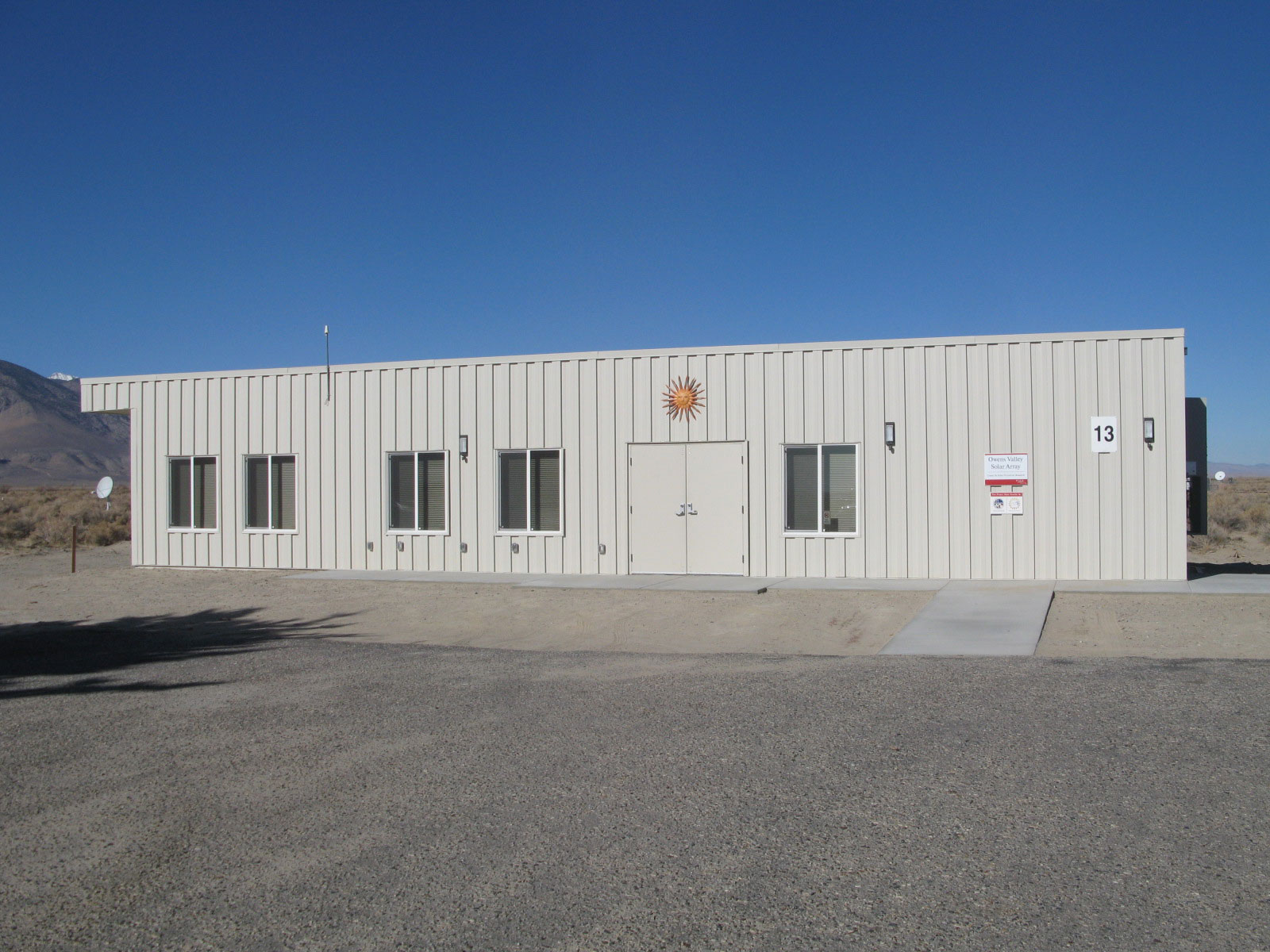
View from the southeast of the completed control building. Click for larger image.
Electronics Room
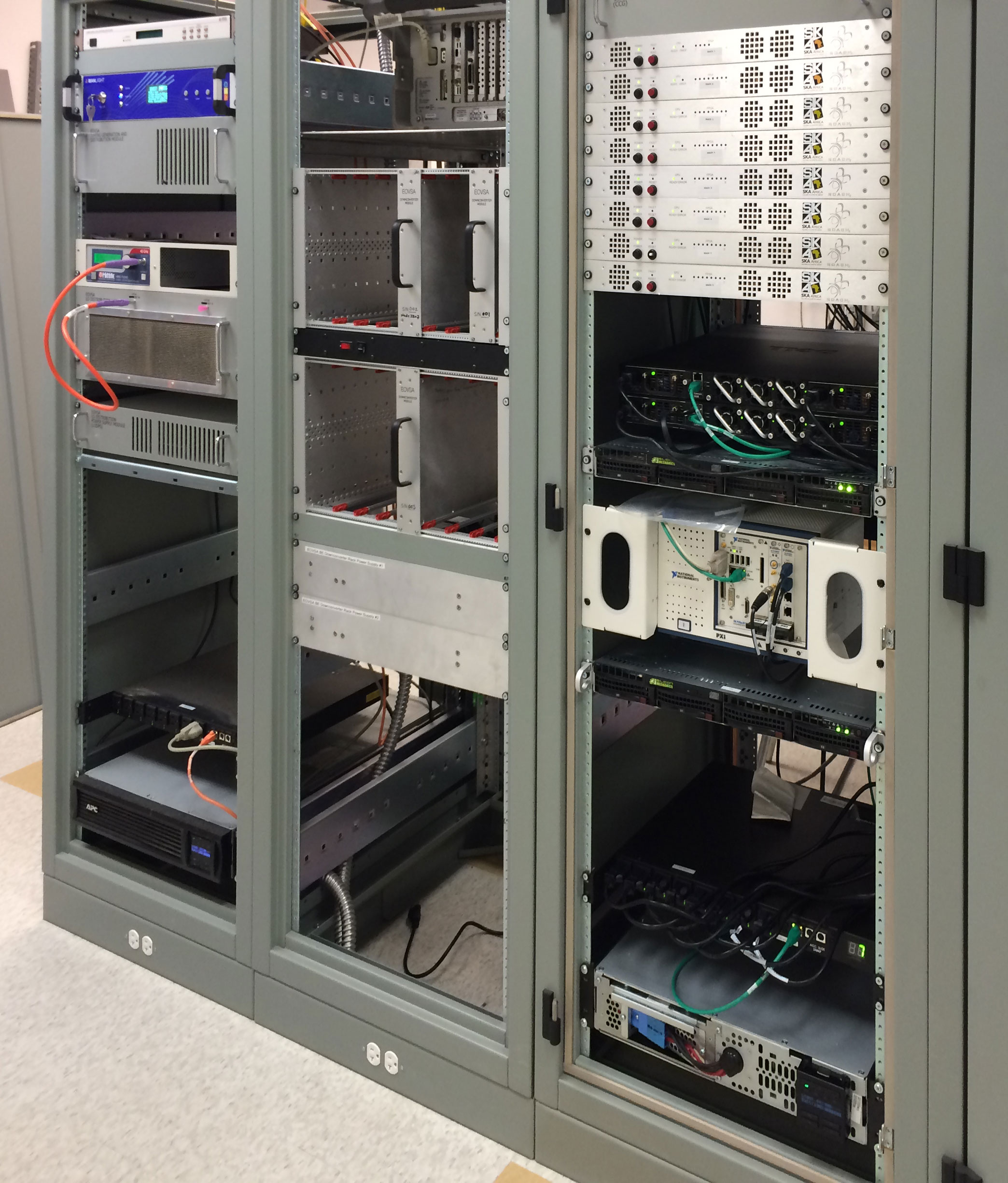
Equipment Racks: Controlling the array and receiving and processing data takes a lot of fancy electronic equipment. At right is a photo of the electronics for the prototype (3-antenna) system, installed in the new control building. The stand-alone rack on the left has the network switches and optical patch panel. The rack at the far end on the right has the local oscillator distribution, and the timing system (GPS receiver, Rubidium timing source, and 1 pulse-per-second distribution chassis). The middle rack on the right has the downconverters and power supplies (this rack will be full when the full array is complete. The nearest rack on the right has the correlator, 10 Giga-bit ethernet switches, and the processing and control computers. A newer photo is also available here showing the complete correlator and additional computers for the full array.
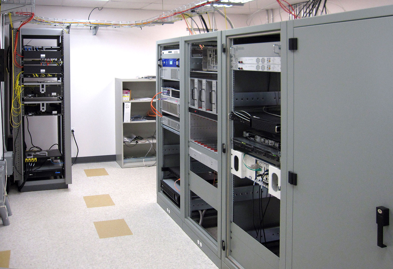
Equipment racks with electronics and analog signal processing equipment for the 3-antenna prototype. Click for larger image.
2.1-m Front Ends
2-m Feeds and Focus Boxes: Kjell Nelin installing the first 2-m front end receiver, with its pair of Peltier coolers and heat sinks extending above and below. This "warm" package, thermally stabilized but operating near ambient temperature, has been installed on the 2-m antennas and contains the Low-Noise Amplifiers, cal source, digital attenuators, and optical transmitters.
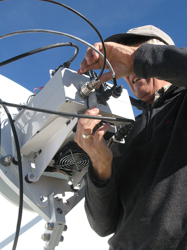
Kjell installing the first warm front-end package for the 2.1-m antennas. Click for larger image.
27-m Front Ends
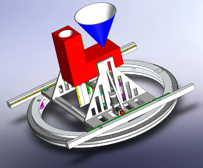
27-m Feeds: The 27-m antennas will have liquid He-cooled receivers requiring specially-designed, high-precision feed horns and cryogenic receivers operating at a system temperature of around 15 K.. The image at right shows one pair all ready to go. Both have the same scaled design to reach a bandwidth of 6:1. The larger horn covers the RF band 1-6 GHz, while the smaller horn covers 3-18 GHz. The overlap permits good cross-calibration. Use of these two horns requires an apparatus to position one or the other feed in the focus. A drawing of the apparatus is available: (click for 3-d model drawing).
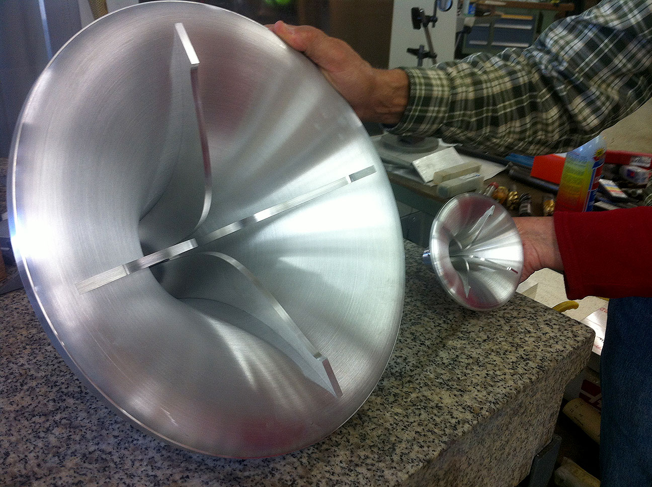
Precision-machined front-end feed horns for the 27-m cryogenic receivers. The large one covers 1-6 GHz, and the smaller one covers 3-18 GHz. Click for larger image.
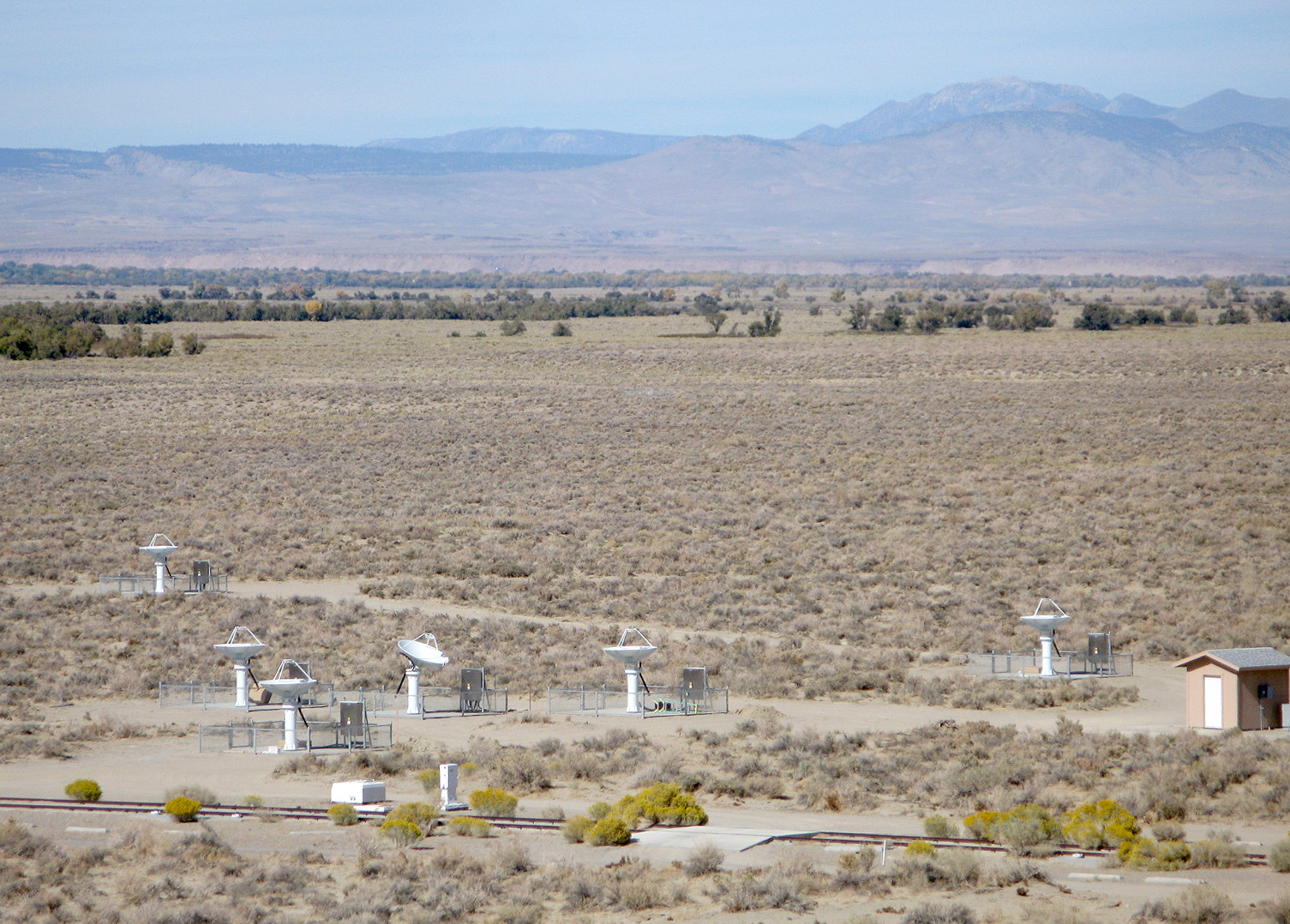
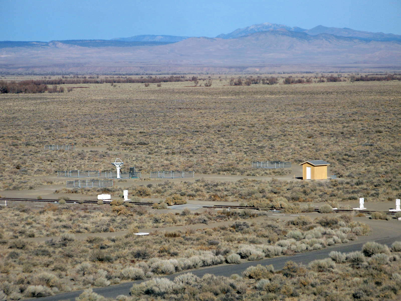
Ants Tracking (with Solar Power)
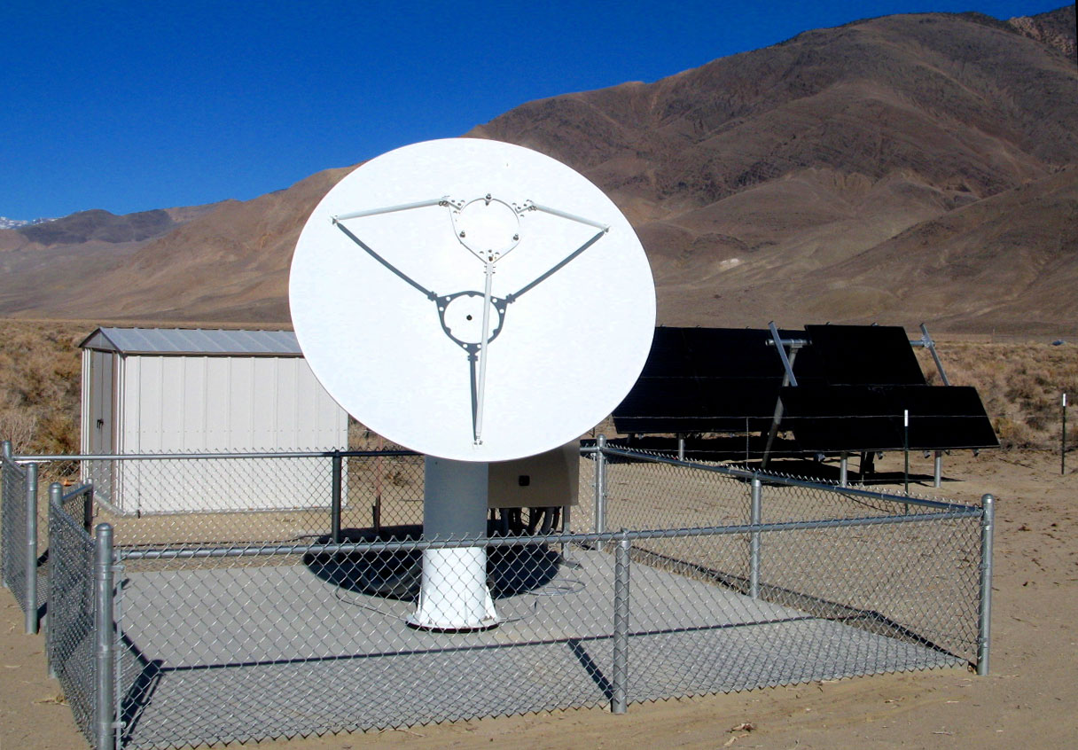
Tracking the Sun: As of 2014 Jan 11, we have 9 of the 2.1 m antennas tracking the Sun, as well as the 27-m antennas. This month we are installing the remaining front ends on the antennas and analog downconverters in the control building. The outer two antennas will use solar power stations. Here is a photo of antenna 12 and its solar power station (click for solar panels and shed in the background). The station is online! (click for current conditions at antenna 12).
Three of the inner array antennas tracking the Sun. Click for larger image (with 4 antennas).